When designing a space capsule that is both safe, lightweight and actually possible for us to build, it is important to break the capsule down in sub-systems. This makes it possible to maintain the overall picture of what needs to be designed and in what order, and what influence the different systems have on each other.
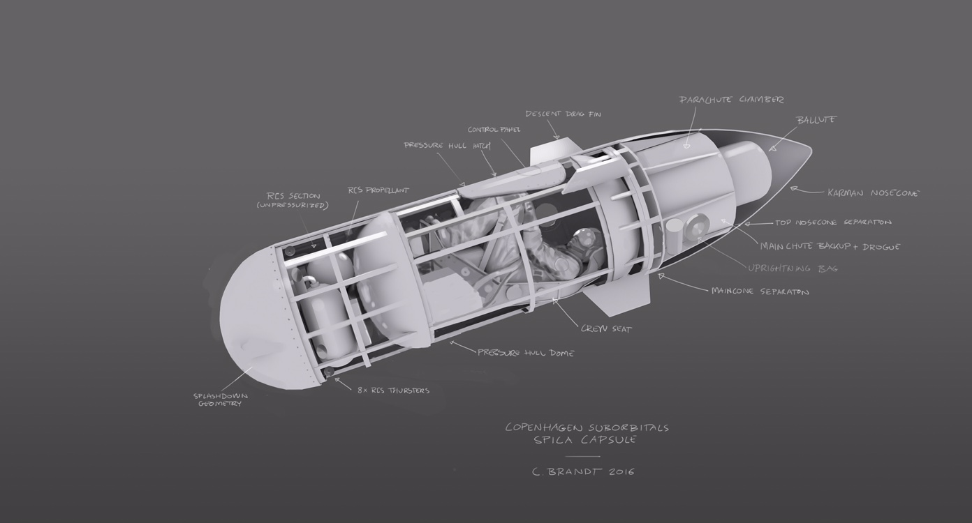
The first capsule we build will be a so called boilerplate model of the pressure hull made in steel. The advantage of using steel is that it’s fairly cheap and easy to work with. Because we’re using steel for the boilerplate capsule it will outweigh the final capsule with quite a lot. Where the final capsule has a mass budget of 300-350kg (including astronaut), there’re no restrictions on the weight of the boilerplate capsule. It’s primary purpose is to achieve a sensible and practical spacecraft layout.
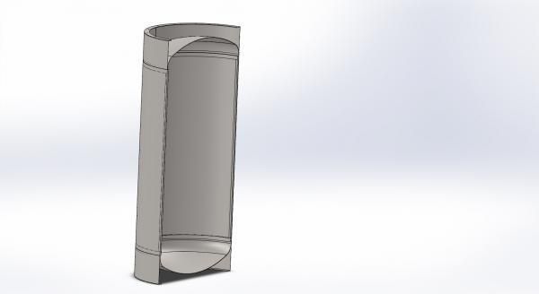
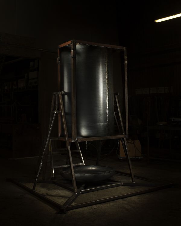
Above on the left is a cross section of the boilerplate model, which we have been building. On the right see the basic structure almost finished. The boilerplate model is 955 mm in diameter which is exactly the size we expect of the final capsule. In addition to the interior design of the capsule, we also have some other ideas for what the boilerplate capsule can be used for. Which of these are realized and in what final form is still unknown.
Hatch design
Hatches in a pressure bearing construction is a giant headache, as such a “foreign body” in a nice cylindrical surface is pure poison for the strength of the construction. We will certainly test several different hatch concepts on the boilerplate model, probably under both pressure and vacuum. Again, a boilerplate capsule will be of great help to us. If a hatch design is discarded, we can just cut it out, roll a suitable plate and then weld it into the hole. It’s so easy when everything is made of steel.
Drop tests
Another thing that we can use a boilerplate model for is to perform drop tests, to evaluate different deformation structures. These will reduce the shock effect on the astronaut when the capsule has the splashdown when landing. Whether it’s from a crane in a port or if we’re so lucky that we get the chance to throw it out off an airplane we’re not sure.
Pressure- and vacuum testing
With the pressurized boilerplate capsule we can evaluate feedthroughs and the strength of the different joints. Specifically, the hatch must be tested and validated in the capsule to the extent that it is so stable and reliable that we dare rely on it as the only protection against an unpleasant end.
We might also use our old autoclave. to simulate the vacuum of space. The autoclave is just big enough for the boilerplate capsule to fit into the pressure chamber. Since the autoclave is equipped with an effective vacuum pump, we can evacuate the autoclave almost completely, which reminds a lot of the conditions in space. We might be able to use this to train our astronaut candidates for a real trip into space. Of course, we must have several unmanned tests and various safety devices that can restore the atmospheric pressure in the autoclave in seconds, but in the end, we’ll be able to train different “unpleasant failure scenarios” with a person in the autoclave.
When we get a bit further in the design process we will begin to add more of the identified systems to the boiler plate model. This gives us a good starting point for the next iteration, where we will look into the right materials and manufacturing processes.
Below we’ve a video about the construction of the boilerplate model.
The capsule stand
We will be working a lot on the boilerplate capsule for long periods of time while it also will become heavier. Therefore, the capsule group has, in parallel with the capsule, built a stand for the capsule to use during its development period. The purpose of the stand is primarily to give us the possibility to easily unpack and pack it after a day’s work in the workshop. Martin has designed the stand so that the capsule can be positioned both in vertical and in horizontal.
-
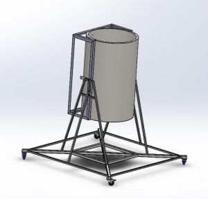
- Illustration: CS
-
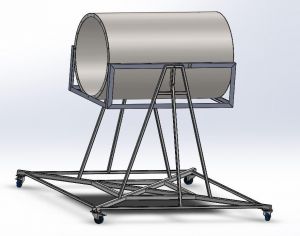
- Illustration: CS
-
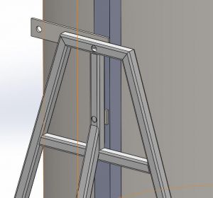
- Illustration: CS
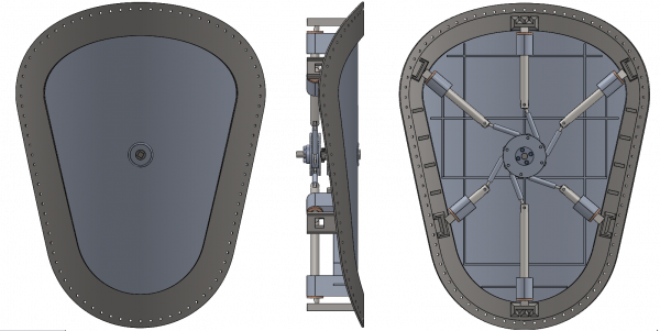
One end of the capsule (the top) has been fitted with a flange with the bolt holes inside the capsule. The endcap has been fitted with a similar flange, which means that we can bolt on the endcap on the capsule from the inside, after we’ve cut a hole for the hatch on the side.
The center of gravity is located roughly in the axis of rotation on the cradle, so it will eventually give the astronaut candidate an opportunity to try to experience an (inadvertently) tumble-down trip through the atmosphere. We can, for example, use it to ensure that the seat and harness will fixate our astronaut so that the limbs cannot hit any sharp or pointed objects inside the capsule.
Dear Copenhagen Suborbitals guests
We'll get right to it: We need your help to run Copenhagen Suborbitals. This is a 100% non-profit project driven by sheer joy and hard work. We survive on donations averaging about $10, that we use to pay for raw materials, tools, our workshop, electricity and most importantly, rocket fuel. The entire CS team are unpaid volunteers, building rockets in our spare time. If this project brings you joy, please donate to keep it running. Thank you.
You can also donate via Paypal from our Support Us page


