Spica will be powered by a 100 kN liquid bi-propellant engine running on liquid oxygen and ethanol just like our experimental BPM5 engine. Spica and the so far unnamed capsule will have a diameter of 955 mm, a total height of about 13 meter and a Gross Lift Off Weight (GLOW) of 4000 kg of which 2600 kg will be propellant. Thus Spica is a significantly larger rocket than our own HEAT-1X and will by a far margin be the largest rocket ever build by amateurs.
The engine will be fed in a pressure blow down combined with an active pressurisation system. Thus the propellant tank pressure will be maintained at the initial pressure for the first part of powered flight by a high pressure system. The implementation of such an active pressure regulation system results in a drastic overall performance increase and lower GLOW, it comes at a price of higher complexity though.
Engine specifications and dimensions
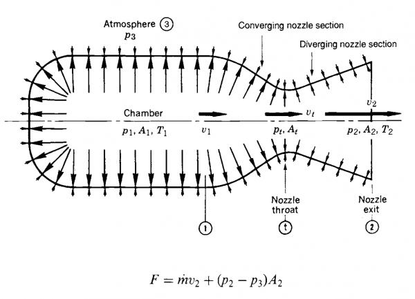
First, as the name indicates it will be a 100 kN engine. But 100 kN is not just 100 kN when it comes to rocket engines. A rocket engine’s power is dependent on the surrounding pressure. The higher we get into the atmosphere and the less the surrounding pressure will be, the thrust of the engine will increase. The amount of additional thrust depends entirely on how the engine’s nozzle is dimensioned and can be easily calculated. Below we have an illustration of a rocket engine and some of the overall parameters we work with as well as the expression for the resulting thrust from the engine.
The largest contribution is from the product of mass flow and exhaust gas average velocity. Next, we have a contribution from the product of the exit area and the difference between the surrounding pressure and the pressure in the exit plane. It is clear that the force is greatest when p3 is 0, i.e. in vacuum.
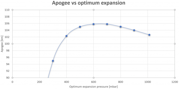
It is also clear, however, that if p2 is less than p3 then we have a negative contribution! Thus, if the nozzle opening is too large, it gives a negative contribution at low altitude until we reach the height to which the nozzle expands. So, there is a small optimization task in tuning the expansion of the nozzle to ensure that we overall get the most of the fuel over the entire flight. I have made a series of simulations, all based on an engine that is constantly burning 45 kg of propellant per second. However, the expansion of the nozzle differs between simulations. The smallest nozzle is optimized for sea level, i.e. with an exit pressure (p2) of 1,013 bar, the next is optimized for 900 mbar, then 800 mbar and so on. Below I have plotted the apogee as a function of the optimum expansion of the nozzle.
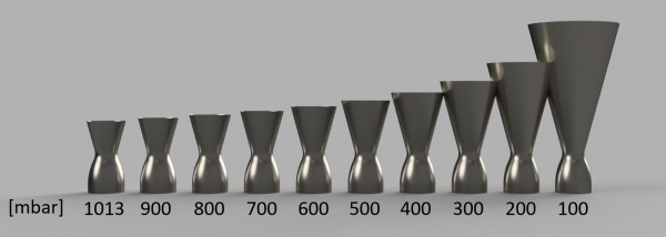
On the left side of the graph, the nozzle is optimized for vacuum, on the right side it is optimized for sea level. As seen, very large nozzles optimized to 300 mbar or less give a significant negative contribution and overall the rocket does not get very high. About 600-700 mbar is optimal for our 100 kN engine. If we get closer to a nozzle optimized for sea level expansion, we do not get enough of the gas expansion in the nozzle. For manufacturing purposes, we will probably opt for an optimal expansion to 700 mbar. It corresponds to the air pressure at approx. 3000 meters altitude. We have outlined the different nozzles below, so you can see them in relation to each other.
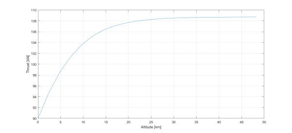
If we expect to achieve 90% of the theoretical performance for LOX and 75% ethanol, and we optimize the nozzle for expansion at 700 mbar, the thrust of the engine as a function of height will look as below. So we start at sea level with about 90 kN. At optimal expansion at an altitude of approx. 3000 meters we reach about 96 kN and shortly before MECO at approx. 32 km we reach about 108 kN. So the engine should probably be called BPM108.
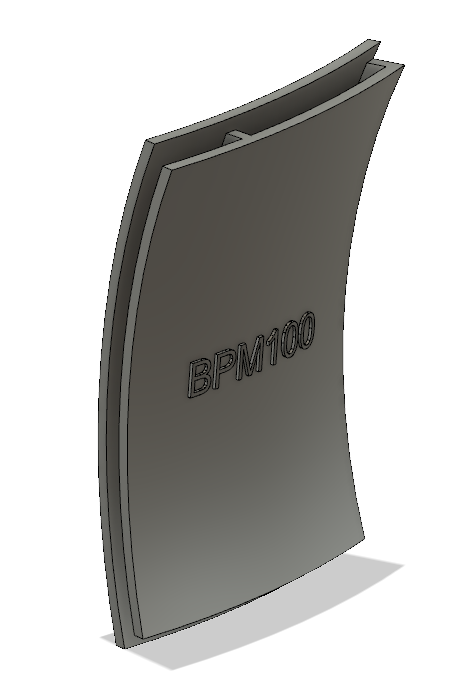
BPM100 is designed as a regeneratively cooled engine like BPM5. However, there are some significant differences. We will try to make the engine in stainless steel this time. It offers less heat conduction compared to mild steel but there are other people out there who build engines in stainless, so we should be able to as well. It spares us the time consuming process of nickel plating the combustion chamber. Something that we will have difficulties to do in this size anyway.
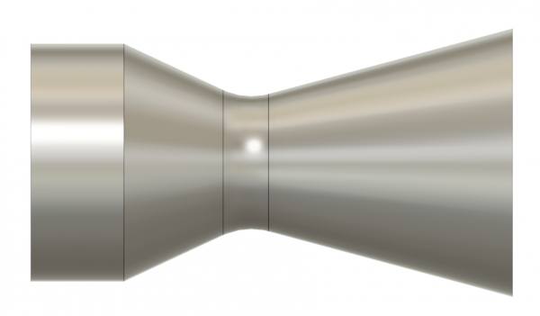
But how big will the engine be? I have made a rough outline of the inner part below. The total length is 900 mm, the throat is 250 mm in diameter. The cylindrical part has a diameter of 420 mm. By comparison, the BPM5 is 100 mm in diameter on the cylindrical part!
We have tried to make the production a little easier for ourselves by having only one tricky section. The upper part is a simple cylinder, then follows a cone, which passes into a double-curved throat section, which again passes into a cone. The hard part is, of course, the throat section. The rest can hopefully be made in rolled sheets. But the throat, it’s a bit more tricky. Here we have, at least on an experimental basis, tried something new; metal 3D print!
The tricky part of the nozzle (throat) has a height of only 85 mm. It can certainly be printed 3D, the question is primarily if we can find a print service that can make it a price that CS can pay.
Engine Injector
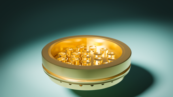
We’re developing a new coaxial swirl injector for our BPM100 engine. Before going full scale we will test the new injectors in our proven BPM5 engine. Here you can see the old BPM5 shower head injector to the right and the new injector to the left.
There are two main reasons for this. First, we would like to validate that the engine is actually performing as expected with these injectors. Next, and at least as important, we would like to practice the manufacture of that kind of injector on a slightly smaller scale before we move on to the very large one. It is a bit experimental and the technique must be spot on for it to work well.
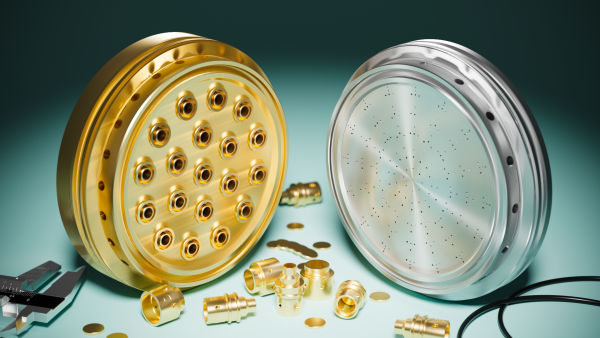
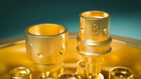
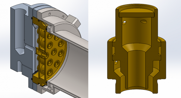
There are 19 swirlers in a BPM5 injector. These each consist of three parts that are soldered individually in one process. The picture shows the inner and outer parts of an element. The recess in the middle of the inner part is filled with solder paste before inserting it into the outer part. In addition, the lid at the top is also put into place with a good amount of solder paste.
We solder these elements with our induction heater in a glass tube filled with nitrogen. It provides a nice surface on the brass element as there is virtually no oxygen to react with the surface.
We have good control over the individual element solder process. The difficult part is to solder it all into one full injector assembly. Here we take a look from the back of the entire injector to see what really needs to be soldered. In the picture the middle part on the left side, i.e. the plate that makes the division between LOX and ethanol (the lids at the top of the elements are also removed). This must be soldered without error to all 19 elements. Likewise, all 19 elements must be soldered to the main body of the injector. So in this injector we have 38 solder joints that all need to be perfect at the same time.
Initially, we had intended to do that soldering in our ceramic oven. However, we are a little uncertain whether we can control the temperature accurately enough. The temperature window from melting the solder paste and melting the brass itself is not very big. So instead, we have come up with a smarter plan where we do not risk heating up too much.
The idea is to make a mini retort where the injector is inside. This is then heated by adding heated nitrogen. The retort can therefore not be warmer than the nitrogen we supply and if we can control the temperature of nitrogen we can thus control the temperature of the retort. The nitrogen is taken from a 200 bar bottle and passed through a long stainless steel pipe which is resistively heated, i.e. by simply running current through it.
Follow the development in these blogs
Dear Copenhagen Suborbitals guests
We'll get right to it: We need your help to run Copenhagen Suborbitals. This is a 100% non-profit project driven by sheer joy and hard work. We survive on donations averaging about $10, that we use to pay for raw materials, tools, our workshop, electricity and most importantly, rocket fuel. The entire CS team are unpaid volunteers, building rockets in our spare time. If this project brings you joy, please donate to keep it running. Thank you.
You can also donate via Paypal from our Support Us page


