It is about time with an update on the BPM100 engine. Let’s start by looking at the dimensions and engine specifications.
First, as the name indicates it will be a 100 kN engine. But 100 kN is not just 100 kN when it comes to rocket engines. A rocket engine’s power is dependent on the surrounding pressure. The higher we get into the atmosphere and the less the surrounding pressure will be, the thrust of the engine will increase. The amount of additional thrust depends entirely on how the engine’s nozzle is dimensioned and can be easily calculated. Below we have an illustration of a rocket engine and some of the overall parameters we work with as well as the expression for the resulting thrust from the engine.
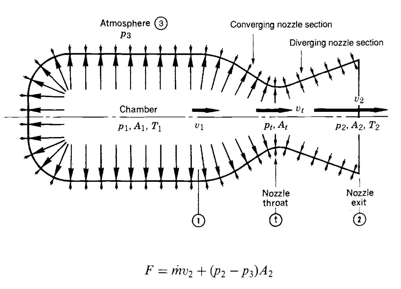
Simplified pressure conditions in a rocket engine. From G.P. Sutton “Rocket Propulsion Elements 7th Ed.”, John Wiley & Sons Inc.
The largest contribution is from the product of mass flow and exhaust gas average velocity. Next, we have a contribution from the product of the exit area and the difference between the surrounding pressure and the pressure in the exit plane. It is clear that the force is greatest when p3 is 0, i.e. in vacuum.
It is also clear, however, that if p2 is less than p3 then we have a negative contribution! Thus, if the nozzle opening is too large, it gives a negative contribution at low altitude until we reach the height to which the nozzle expands. So, there is a small optimization task in tuning the expansion of the nozzle to ensure that we overall get the most of the fuel over the entire flight. I have made a series of simulations, all based on an engine that is constantly burning 45 kg of propellant per second. However, the expansion of the nozzle differs between simulations. The smallest nozzle is optimized for sea level, i.e. with an exit pressure (p2) of 1,013 bar, the next is optimized for 900 mbar, then 800 mbar and so on. Below I have plotted the apogee as a function of the optimum expansion of the nozzle.
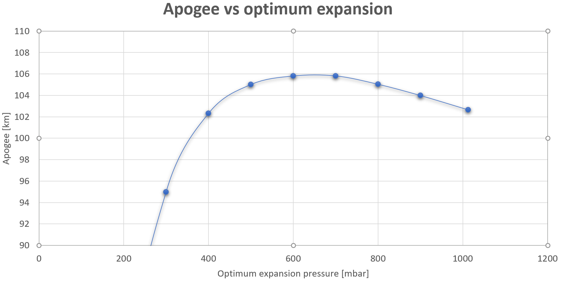
Apogee as a function of the nozzle expansion pressure.
On the left side of the graph, the nozzle is optimized for vacuum, on the right side it is optimized for sea level. As seen, very large nozzles optimized to 300 mbar or less give a significant negative contribution and overall the rocket does not get very high. About 600-700 mbar is optimal for our 100 kN engine. If we get closer to a nozzle optimized for sea level expansion, we do not get enough of the gas expansion in the nozzle. For manufacturing purposes, we will probably opt for an optimal expansion to 700 mbar. It corresponds to the air pressure at approx. 3000 meters altitude. For fun, I have outlined the different nozzles below, so you can see them in relation to each other.
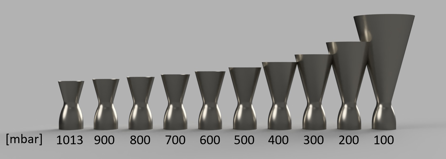
BPM100 nozzles optimized for pressure from 1 atmosphere to 100 mbar.
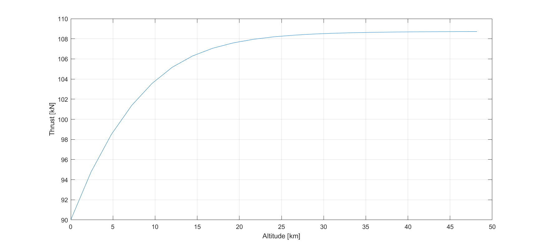
If we expect to achieve 90% of the theoretical performance for LOX and 75% ethanol, and we optimize the nozzle for expansion at 700 mbar, the thrustof the engine as a function of height will look as below. So we start at sea level with about 90 kN. At optimal expansion at an altitude of approx. 3000 meters we reach about 96 kN and shortly before MECO at approx. 32 km we reach about 108 kN. So the engine should probably be called BPM108.
BPM100 is designed as a regeneratively cooled engine like BPM5. However, there are some significant differences. We will try to make the engine in stainless steel this time. It offers less heat conduction compared to mild steel but there are other people out there who build engines in stainless, so we should be able to as well. It spares us the time consuming process of nickel plating the combustion chamber. Something that we will have difficulties to do in this size anyway.
But how big will the engine be? I have made a rough outline of the inner part below. The total length is 900 mm, the throat is 250 mm in diameter. The cylindrical part has a diameter of 420 mm. By comparison, the BPM5 is 100 mm in diameter on the cylindrical part!
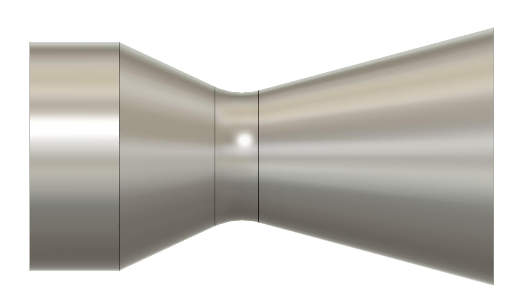
Outline of the inner part of BPM100.
We have tried to make the production a little easier for ourselves by having only one tricky section. The upper part is a simple cylinder, then follows a cone, which passes into a double-curved throat section, which again passes into a cone. The hard part is, of course, the throat section. The rest can hopefully be made in rolled sheets. But the throat, it’s a bit more tricky. Here we have, at least on an experimental basis, tried something new; metal 3D print!
The tricky part of the nozzle (throat) has a height of only 85 mm. It can certainly be printed 3D, the question is primarily if we can find a print service that can make it a price that CS can pay. To find out, I have sent 1/16 of a throat section out to print at a French company a few days ago. As shown below, I have drawn a rudimentary cooling channel between the double walled construction.
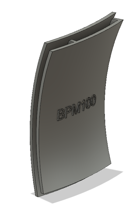
The company is printing in a stainless alloy and it will be very exciting to get it home for inspection. As soon as it arrives in DK, we will first evaluate if it is something we can weld, we need to measure the strength and probably measure the heat conductance. It is all very exciting and we will return with more on this next week once we have it in house!


15 Comments
Comments are closed.