The electronics group in Copenhagen Suborbitals has used the somewhat quiet period after the launch of Nexø II to decide, among other things, which EDA (Electronic Design Automation) software is best suited for us.
We have chosen KiCad, a freeware schematic capture and PCB layout tool maintained and developed by a group of independent programmers.
The fact that KiCad is free is of course conducive for an application to be chosen as a new standard tool at Copenhagen Suborbitals, but several specifications have been important in the evaluation of KiCad by the electronics group.
One of these is the ability to work with symbol and part libraries that are centrally located on a GIT server. Thus we do not have to synchronize local libraries when exchanging designs at different stages of development, and can also ensure some standardization of our locally defined components.
Another important proponent of choosing KiCad is the ability to include 3D representations as part of the component definitions.
Kicad’s well-functioning tool for importing Eagle designs is also an advocate, many of the our designs are in this format, and many of the electronics group’s members have worked with this tool.
We are increasingly using the opportunities that our access to SolidWorks gives us to share designs across design- and workgroups, which both facilitates data delivery and specifications, and greatly reduces the number of nasty surprises.
There are, of course, a certain amount of frustration to endure while getting used to using a new EDA tool, and all members of the group has been sitting with a very clenched expression when yet another oddity (to put it nicely) in the tool’s user interface surfaces.
We have found that KiCad version 5 offer the features we want. But we have also found that the available documentation is written for version 4, so many of the buttons and procedures have been changed when trying to use the descriptions to work further inside the tool.
To get to know the tool and its intricacies, a design flow was initiated, from napkin sketch over schematic capture and PCB layout, to finished 3D model and functionally tested printed circuit board.
For the author, the choice of sample design was a keyboard interface board. The preliminary exercises on a provided sample design showed that the hotkeys you use the most are in east and west, and you have to move your hand here and hither while working.
During schematic capture, while connecting the components, the keys W, K and J are used endlessly, and the hand position is frankly more than tiring.
During layout, the author uses the keys ESC, D, PgUp, and PgDn to place and edit tracks and vias, which results in constantly moving one’s hand from one side of the keyboard to the other.
Well, then you just grab a numeric keypad from the shelf with PC accessories, and make your own hotkey definitions. No, you’ll learn that it’s not that easy. First, the arrow keys on the KiCad numeric keypad are always decoded as arrow keys (at least on Windows 10), whether or not the keypad is in NUM LOCK mode. You cannot use the arrow keys as hotkeys in KiCad, and then you lose the use of 4 of the 18 keys on the keypad.
Secondly, we still talk a lot in the group about how to use the tool, and of course help each other get familiarized with using the tool. What one is struggling with, another has already mastered, and can explain about. And if you have your own set of hotkeys in your head (or the manual), talking together quickly becomes pretty confusing.
So it all boils down to moving hotkeys around without changing (too much of) the hotkey definition. Then there is only one way forward if you insist on wanting to use a numeric keypad to solve the task of avoiding the flying hand position: The numeric keypad must have programmable keys.

So the solution ended up being an Arduino-inspired construction. The author’s skills in algorithm design are about as sharp as Grandma’s most worn down rolling pin, so once again the Italian microcontroller board series will be called upon.
The processor of choice is the Atmel ATMEGA32U4, as it can be made to act as a USB keyboard without too much trouble. This processor is featured in the Arduino Leonardo. And a Leonardo board was available in the junque box!
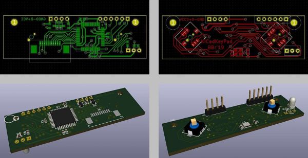
A schematic was quickly put together to decode the 4×5 matrix of the keyboard. Two small 5-way navigation sticks were added for good measure, in case any gifted ideas would need to be implemented at a later date. A dual color LED was added to indicate the chosen keypad mode.
Editing or adjusting the schematic, specifically selecting the ports on the ATMEGA to facilitate easy routing of the board, was easy and straightforward, immediately earning a few stars in the review chart.
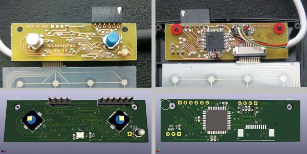
The board layout work flow was also reasonably easy to learn, but of course not entirely without sighs and grinding of teeth. For example, why can’t you move a via unless you move its center outside the area it covers? Although there are grid points within the covered area? Argh! For the author, a lot of ingrained editing philosophies need to be replaced or adjusted, so even with more than twenty-five years of experience in advanced EDA, the learning curve is anything but flat.
The coding of the processor then took a lot longer than the practical construction, not only because of the grandma’s rolling pin, but also because the Arduino documentation, like kicad’s, is out of step with the updated world. Among other things, Arduino in their keyboard library uses a different ASCII table than the table the documentation refers to, and some of the standard characters are omitted; but it is a « secret » you have to uncover yourself.
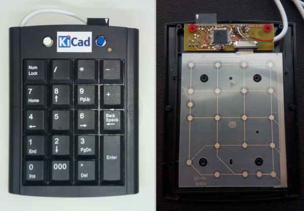
However, a keyboard has successfully been made, based on a cheap standard numeric keypad of Chinese origin that meets the author’s requirements. One of the small navigation sticks is used to select the mode appropriate for the four main KiCad modes: Schematic Capture, Symbol Library Editor, Board Layout, and Footprint Library Editor. The NUM LOCK key has as the only key, retained its well-known function, all others have now been assigned new « values » and small macro-like key sequences.
The « values » of the keys are defined in tables placed in the sketch that makes up the Arduino part. Not super easy and service friendly, but at an acceptable nerd level for the author.
And the keyboard actually makes the operation of Kicad easier for the author. A lot can be done with hotkeys so that there is no need for constantly using right-click drop-down menus, or clicking on buttons located on the outer edges of the user interface. A full size keyboard is still mandatory for text input, but the flying hand operation is greatly reduced.
There have been slight adjustments to the key definition tables along the way (and there are certainly more to come), and it has also been nice to have a small key function chart handy close to the keypad, but that’s no matter.


2 Comments
Comments are closed.