Dear readers,
Not long ago we received a nice item from PH Spaanteknik which has once again helped us with some CNC machining. Jakob has spent a lot of hours this time and we are very grateful.
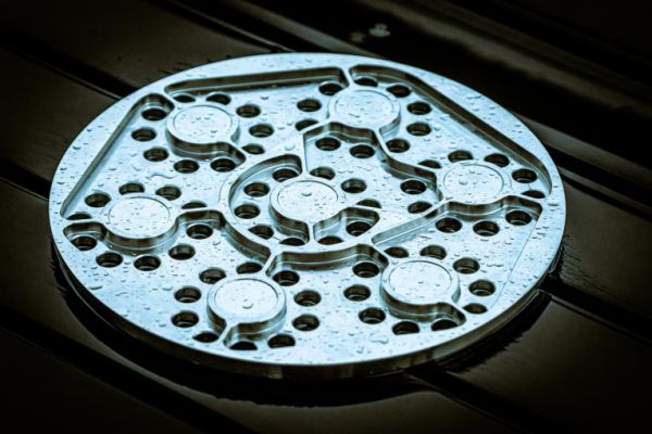
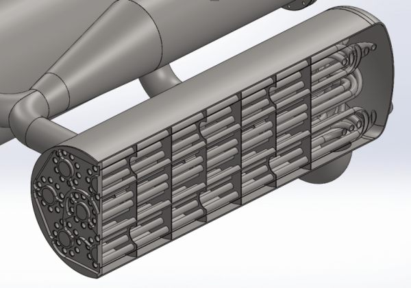
Illustration: Thomas Pedersen
So, what did Jakob mill for us? Well, he made the first prototype of something there’s going to be in our Spica rocket. It’s a nice gas manifold in stainless steel. As is clearly seen, it’s designed for CNC milling from the beginning. It would have required quite a lot of work on own little Deckel mill.
And what is its purpose? Yes, it’s hard to see, but it’s for the heat exchanger on Spicas BPM100 engine. As you probably remember, Nexø II flew with a 300-bar helium tank, which we used to maintain the pressure in the fuel tanks. The idea was to do the same with Spica. But we would need a lot of pressurized gas with two approx. 2,400-liter fuel tanks. With 20 bars in the tanks we would need approx. 48,000 standard liters (SL) of gas. Nexø II had 600 SL of helium on board, so we would need quite a lot of the expensive composite tanks if we choose that method. So, we’ll try something a little smarter.
The idea is to bring the gas for pressurization in liquid form instead. We have also previously seen that nitrogen is an excellent gas to use as pressurization gas, so we’ll also switch from helium to nitrogen. Nitrogen has an expansion factor of approx. 700 from liquid to gas, so the 48,000 SL can be brought as 68.5 liters in liquid nitrogen. Of course, to move nitrogen from liquid to gas, we need energy (heat), luckily that’s one thing that there is a lot of in a rocket engine. The perfect solution would be to get the heat from the engine. It does, however, provide a complicated interaction between the engine and the pressurizing system and, not least, it provides a pressurizing system which can only be tested in a full engine test. We won’t go so far.
Our system will instead consist of a separate burner which provides the necessary heat to evaporate the nitrogen. And when we are heating anyway, we will heat up the gas more so that it will expand more and thereby increase the factor of expansion from 700 to around 1000. By doing so we only need about 50 kg of nitrogen to propel the fuel.
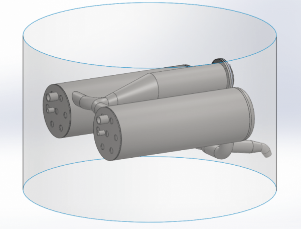
With a burning time of just about 50 seconds, if we run full throttle all the way to MECO, then we need to evaporate 1 kg of nitrogen per second. And additionally, we would also like to heat it to about 100 degrees. This gives a total energy consumption of 500 kW. Ethanol has a calorific value of about 30 MW/kg. We dilute our ethanol with 25% water, so the calorific value is probably only about 22 MW/kg. If we are to extract 500 kW out of such a burner, we must burn approx. 20 grams of fuel per second. Now, of course, it won’t be 100% efficient. The efficiency is one of the things that we’ll find during testing. From the above, however, it is hardly particularly clear how the manifold is included in such a burner and heat exchanger, so let’s look at Thomas Madsen’s design in Solidworks. First, look at the overall system. We see here the burner in the middle and two heat exchangers. Of course, it all fits within Spica’s diameter of 950 mm. The fact that there are two heat exchangers is because there is one for the fuel tank and one for the LOX tank, so the pressure can be controlled individually.
When we look inside one of the heat exchangers, we see a lot of pipes. In these pipes, the nitrogen will flow back and forth surrounded by the outer shell of the heat exchanger. There is 70 meters of tube inside each heat exchanger!
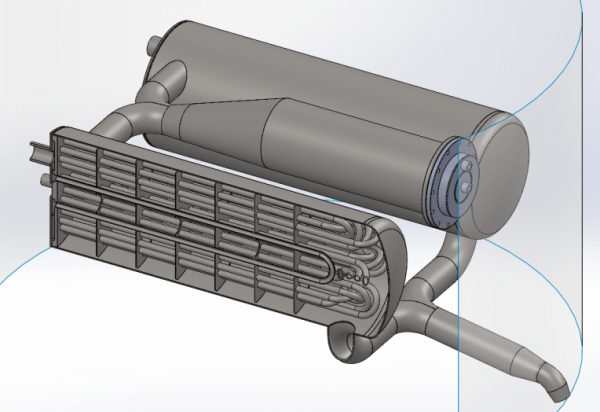
Finally we get to the manifold. In one end of each heat exchanger there is such a manifold which simply allows nitrogen to flow from one set of tubes to the next set of tubes through the heat exchanger. By doing so we get the necessary surface area needed to evaporate and heat 1 kg of nitrogen per second.
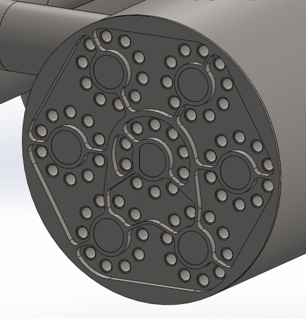
The next step will be to weld all the pipes to the manifold. When it’s done it will be a small work of art and it will be very exciting when we’re going to test it. As can be seen, there is no cooling in the system other than what comes from the hot nitrogen. This means that during operation, both burner and heat exchanger are likely to be red-hot. It will be quite a spectacular sight. It will initially be operated on the BPM5 test stand, although its fuel tanks are heavily oversized for the purpose. Initially, we will probably run water through the heat exchanger rather than nitrogen and simply measure the water temperature at the exit. But soon after that, we will test with nitrogen.


11 Comments
Comments are closed.