Dear readers,
If you follow us on social media, you may have already discovered it, otherwise we will bring you some news. During the past week, we have made the first cuts and weldings for the 100 kN engine! However, it’s not the engine we have started building, but the relatively large teststand for the injector tests.
Designing an engine is largely about designing the injector itself. Looking back at our BPM-5 engine, we started testing single injector elements before we calculated the dimensions of the final injector. These tests were used to accurately determine the pressure drop and discharge coefficient for holes of different diameter. Based on this we could then calculated the dimensions of the final injector which, after manufacturing, was also tested quite thoroughly.
Test of injector elements for BPM-5. Photo: Thomas Pedersen.
From our BPM-5 engine, we therefore have a working teststand for injector test. But where the BPM-5 has a mass flow of about 2.5 kg/s, our 100 kN engine will have a mass flow of approx. 50 kg/s. To get stable measurements, we usually test for around 10-20 seconds, on the big engine, we will need 500-1000 liters of water through the system for each test! Thus, the existing teststand is far too small.
Due to the amount of water needed the teststand becomes quite large. Let’s take a look at a model in SolidWorks.
The upcoming injector teststand consisting of a total of four tanks. Illustration: Thomas Madsen.
As seen in the illustration it consists of four tanks, why now? Well, the cheapest way to build it is to buy the largest pipe our dear sponsor Sanistål has in the catalog and create tanks from that. This means that the tanks will be around 600mm in diameter. As we said, we would like to run a test of 10-20 seconds, so there should be room for 250-500 liters of fluid for both the fuel and oxidizer and in addition there must be room for approx. the same amount of pressurization gas. We therefore conclude that we want an effective volume on each side between 500 and 1000 liters. In order not to make the tanks very tall, each side is divided into a liquid tank and a gas tank, thus we get a total of four tanks on each approx. 400 liters.
To ensure a minimum of pressure loss in the pipes, almost all pipes are 3 inches in diameter. As shown below, you lose almost 1 bar per meter with a 2-inch pipe. It’s not so critical of the teststand, but when we build the Spica rocket, this kind of pressure loss must be minimized in terms of calculating the dimensions and weight of the fuel tanks.
Pressure loss per running meter pipe as a function of the pipe size. Illustration: Thomas Pedersen
As we said, we will need quite large amounts of water per test. It’s not seen in the illustration, but there will be an open pallet tank below the injector so that we can collect and recycle all the water.
Instrumentation on the teststand will consist primarily of a series of pressure sensors for measuring pressure in the tanks and in the injector. In addition, of course, we will also measure the flow. Turbine flow sensors in this size is quite expensive, so we have ventured into making our own venturi flow sensors. The principle of such a flow meter is that a local constriction gives a local higher flow rate and hence a local pressure drop. With a differential pressure sensor, this pressure drop can be measured, and the flow can be calculated. We firmly believe that we can build this our self, rather than buying an expensive turbine flow sensor, so we’re buying some cones, pipes and differential pressure sensors and creates some electronics for it. It will be a little extra project, but it can save us a lot of money. It’s a fun little project, which we will tell you about in a later blog.
Finally, we’re working on the big engine. Well not the engine itself, but some of the infrastructure that will lead towards it. It feels great and we look forward to the next few months where much more of the engine’s design will finally fall into place. And we’ll try to blog about it as much as possible.
Finally, a couple of pictures from the workshop last weekend.
Jop welding together the frame. Photo: Sarunas Kazlauskas.
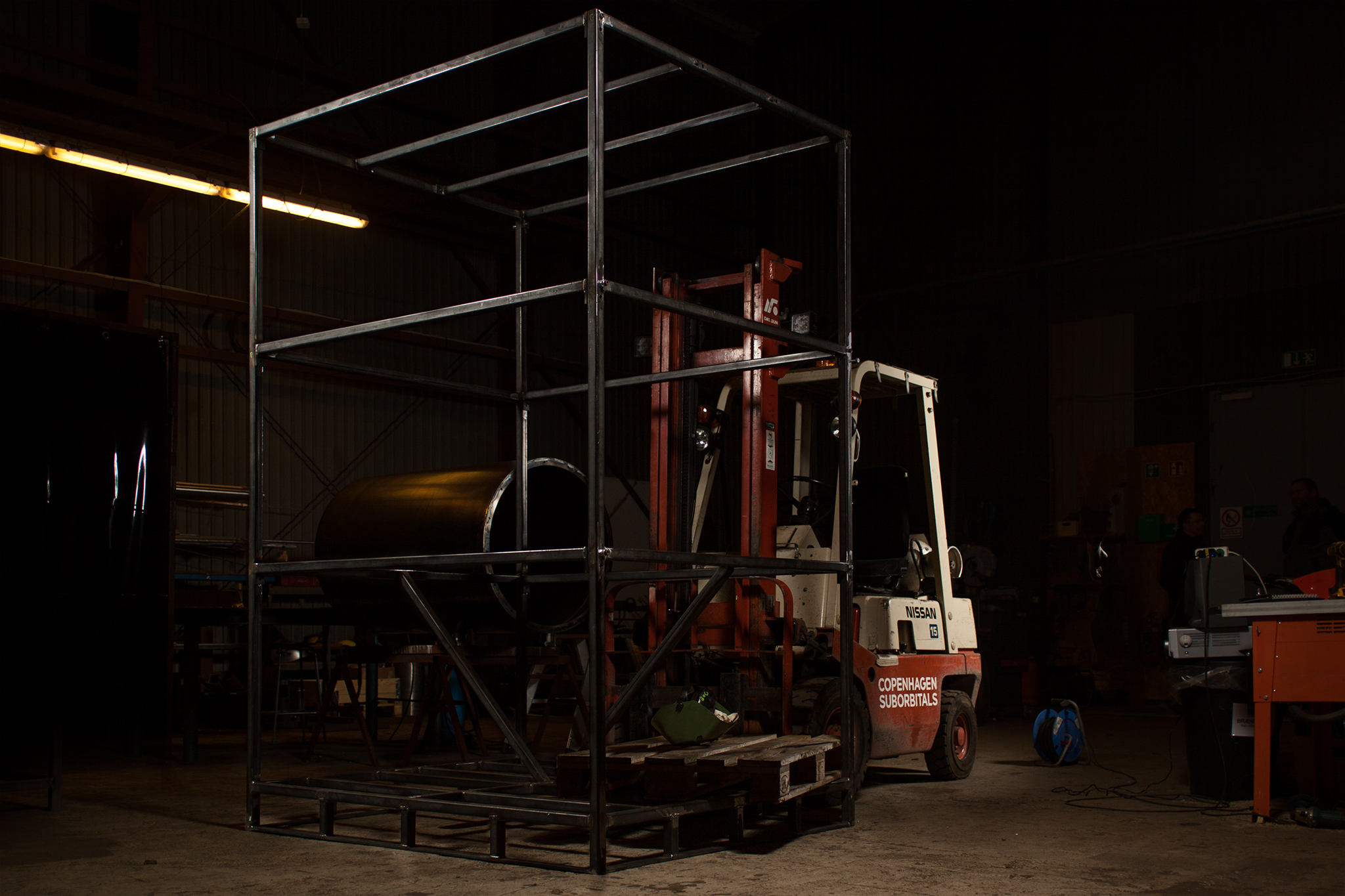
The frame for the teststand half way done. Note the size. Everything will be large for this engine! Photo: Sarunas Kazlauskas.


6 Comments
Comments are closed.