Dear Rocket Friends,
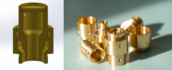
After a bit of getting ready we are now in the process of measuring how our nice little swirlers are performing. As you may remember, we got them milled at PH Spaanteknik and a few weeks ago we got the first of them soldered together for testing.
The test is fairly straight forward as we simply need to measure the flow rate as a function of pressure. In the test setup the pressure drop is given by the pressure in the injector itself minus the pressure of the atmosphere since the water is ejected into atmospheric pressure. In an engine the pressure drop will of course be given by the pressure in the injector minus the pressure in the engine. Moreover, a swirler is designed so that its exit area is substantially larger than the entrance area, thus it is the small entrance holes that put the restriction in flow.
The test stand has two small, cheap flow sensors that can measure the volume flow. In practice, we see that the flow sensors are a little pressure dependent, so to get around this all the water from a test is collected and weighed, so we have a total flow to correct the flow sensor measurement against.
As mentioned in earlier blogs we would like to test these swirlers on a BPM5 engine so we have to dimension them to provide the necesarry flow for a BPM5 engine. This means that we need a flow of 1110 gram/s ethanol and 1450 gram/s LOX. We have played around with the geometry in Solidworks and landed on a design where we can fit 19 swirlers in a BPM5. Distributing the flow into 19 swirlers we need 58 grams of ethanol per second and 76 grams of LOX per second per element. Now, we do not have ethanol and LOX on the water flow test stand, so we have to account for the difference in density which mean that we have to hit a water flow of 68 g/s on the ethanol side and on the LOX side we have to hit a water flow of 67 g/s. The flow sensors measure the volume flow, so it is 68 and 67 ml/s respectively.
For starters we have tested two of the soldered elements. Element # 1 has four Ø1.1 mm entry holes on the LOX side and six Ø0.9 mm holes on the fuel side. Element #2 also has four Ø1.1 mm LOX holes but four Ø1.1 mm fuel holes. The only difference is thus on the fuel side. The immediate data we get from such a test is plotted in the graph below.
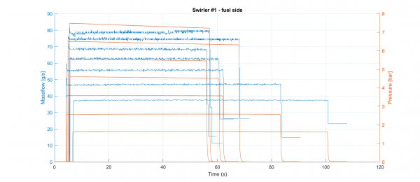
We see a set of nice curves with almost constant pressure and thus almost constant mass flow over a relatively long time. The interesting thing is when you take all this data and plot it as mass flow as a function of pressure. We see this below.
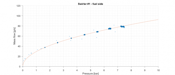
Data is fitted to a function such as y = c * sqrt (x) where the expected flow, q, is given as q = Cd * A * sqrt (2*dP), where Cd is the discharge coefficient, A is the cross-sectional area and dP is the pressure drop. Data is seen to fit really well with such a function. If we take all four measurement series on the two elements it looks like below.
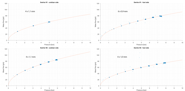
As mentioned, the two elements does not have the same hole configuration. I have listed the hole dimensions on the graphs. The two elements should be identical on the LOX side but we do not see the same flow on the two lefthand graphs. We did however notice that element #1 got better during the test, i.e. we believe it might have been partially clogged with remains from the solder process. Thus element #2 probably shows a more correct flow. The flow on element #2 is 61 g/s, a bit below the desired 67-68 g/s. Looking at the fuel flows we see flows of 51 and 46 g/s at 3 bar for the two elements. This is somewhat lower than the expected 67-68 g/s.
We will continue to test some new elements the coming days but we will also experiment with modifying the parts we already have. Thus we will simply drill the holes up 1/10 mm on some elements and see how they perform to get as much good data as possible.
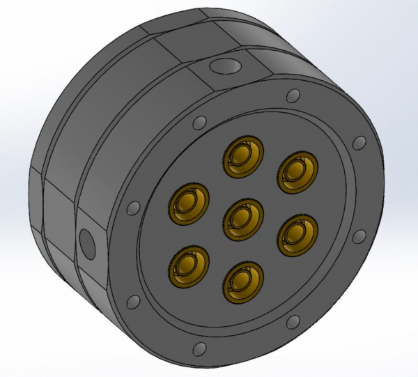
As a further part of our water flow test, we would like to visualize how the cones from these swirls interact with each other. That is why we have put a small 7-swirler manifold into production in HAB North. It gets milled in POM and in this we can then freely mount between one and seven swirlers and see what their spray pattern looks like. With a little luck we can have it ready for testing this coming weekend.


8 Comments
Stephan · 28th August 2019 at 7:31 am
Do all holes have to be same size? Or could you enlarge only half of them for finer flow adjustment?
Jacob Skov Larsen · 22nd September 2019 at 11:05 pm
Hi Stephan,
The holes could in theory be of different sizes, to give even finer control over the flow rates, but the implementation calls for more machining or tool changes in the production phase.
David Lang · 22nd September 2019 at 10:06 pm
what sort of heat load are these going to see when you fire them? is the solder going to hold up?
Jacob Skov Larsen · 22nd September 2019 at 11:08 pm
HI David,
They will see a lot of heat from the combusion process. Luckily, the swirl nozzles are rigously cooled by both fuel and LOX, which should help. No guarantee that hot spots cannot develop locally and burn out elements anyway. Solder joints are however far recessed and the melting point of the solder is above 600°C.
E.Philpott · 23rd September 2019 at 10:24 am
Keep up the excellent work on this very Danish rocket vehicle.
Rosco · 23rd September 2019 at 1:18 pm
Your Copsub guys are world class, doing it all with a dedicated team of professional volunteers is a testimony to your dedication and brilliance.
Keep it up, the world needs some serious inspiration .. Rosco and the Aussie Invader LSR misfits …
Diego Gomez · 29th April 2020 at 7:07 pm
What is the average thrust expected to be produced per element?
Dhrumil Patadia · 11th August 2021 at 8:12 pm
What is the value of Cd for these swirlers ?
Comments are closed.