As you probably remember, our BPM5 engine uses a relatively simple injector technology. Simple in the way that it is a cylindrical disc with a whole lot of holes in which leads fuel and LOX into the chamber.
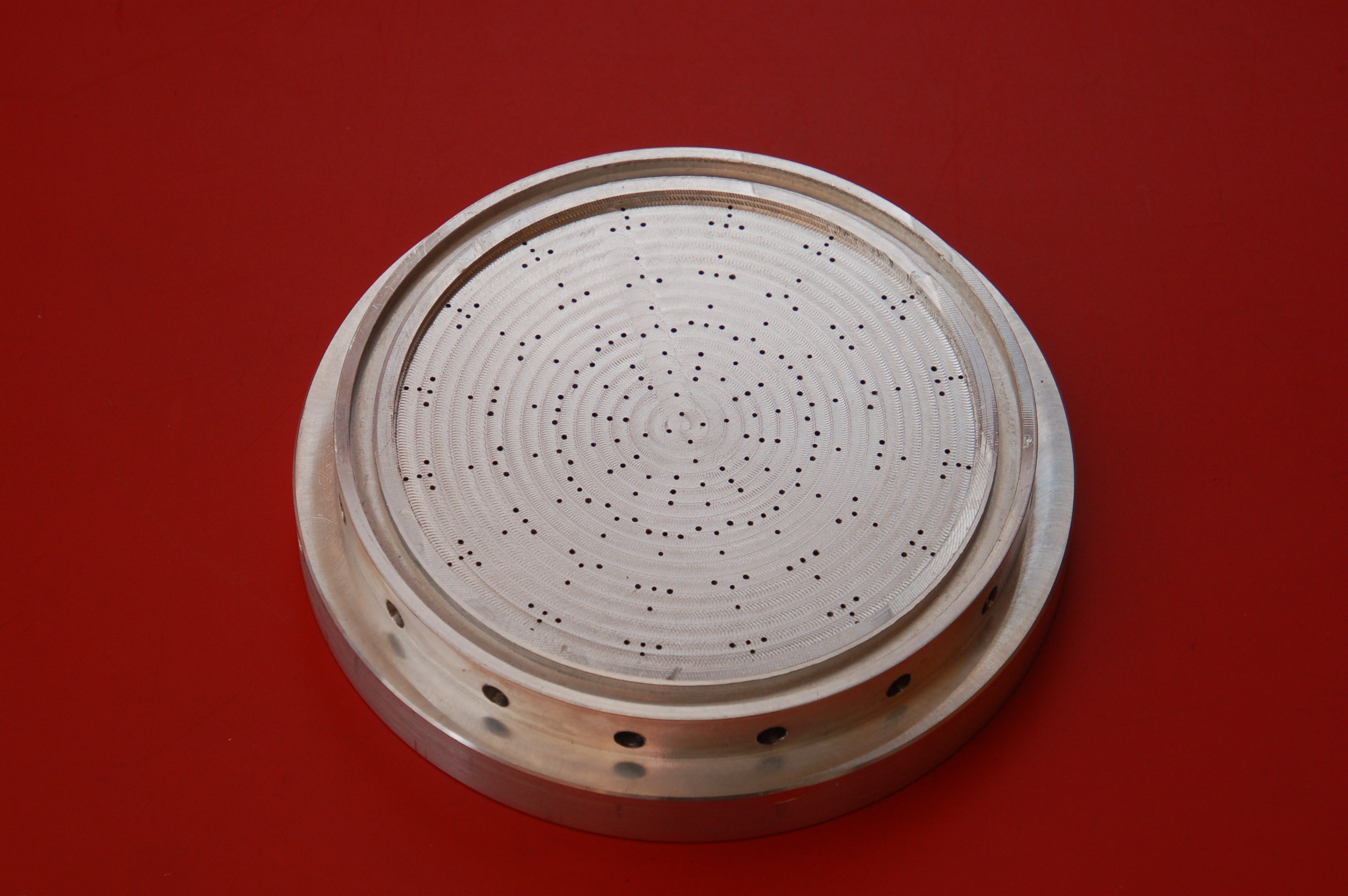
BPM5 engine injector seen from fire chamber side. Photo: Niels Foldager.
Making it requires a 5-axis CNC mill and it caused us a lot of problems in the BPM5 process to access such a machine. With its 20 times higher propellant consumption, a similar injector for BPM100 will actually become a bit of a challenge to manufacture, so we would like to try something a little different. Something that might be made easier, we will therefore try to make an injector based on co-axial swirlers.
And what is a swirler then? Let’s start with a good illustration of a simplex swirler I stumbled upon the other day on television, more specifically in “Christmas with Timm, Markus and Katrine” on Danish DR1. Here, Markus Grigo has to empty a bottle of wine into a pot and to make it go a little faster, he rotates the bottle so that the liquid rotates inside the bottle. The result is a higher flow rate and that the liquid leaves the opening out along the rim and creates a fluid-free zone in the center where air can come the opposite way. A trick many probably know, and the rotating motion of the liquid is the core of a swirler injector.

Markus Grigo illustrates the principle of a swirler. Photo: DR.
In Markus’ example, the flow rate is not so high, it is seen that the flow is not fully developed as one would want it in a rocket engine. With increasing pressure, in an injector one can get the liquid’s speed up and drastically change how the liquid leaves the opening, which is illustrated excellently in the figure below. With high enough pressure, it is seen how the liquid film forms a cone surface which breaks up into tiny droplets. That is what we want in a rocket engine.
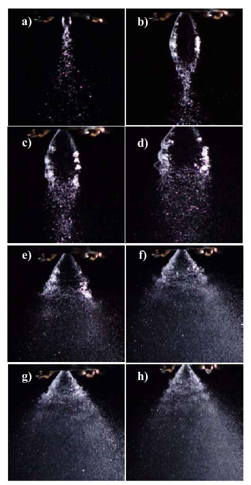
Flow development with increasing pressure for a simplex swirler. From [1].
Markus’ demonstration and the second series of images are made with only one liquid flow, in a liquid-propellant rocket engine we naturally have two fluid streams. And here it gets really beautiful. In a coaxial swirler, we have two fluid streams that both leave the injector as a thin film that each spans a cone. With the correct geometry, it aligns so that the two conical surfaces collide and creates one cone surface that breaks up into tiny liquid droplets, as seen in the illustration below.
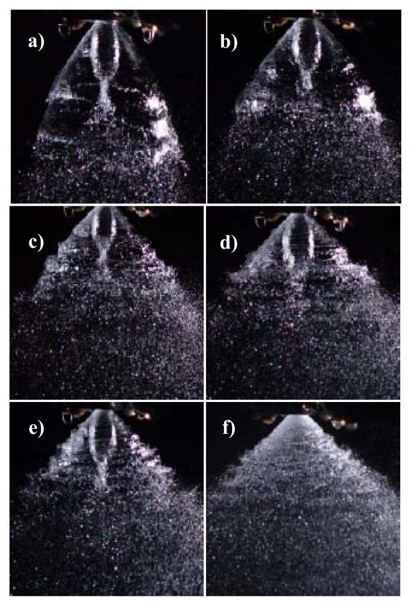
Flow from a coax swirler. It is clearly seen in the first pictures that there are two liquid flows, but at the correct pressure and geometry they collide with one liquid flow. From [1].
It will require some experimentation to get the correct geometry and pressure correct, so the plan is to make a small setup where we can test different injector elements. Both so that we can visually see how the fluid flows out, but of course also so that we can measure flow as a function of pressure. This is something we immediately put into action, and I hope we can get started with measurements in late February.
Our version of a co-ax swirler element could end up looking like below. The element consists of three parts; the outer element, the inner element and the inner element lid. As can be seen, all subjects are quite simple in their geometry and will be quick to make on a lathe, except for the holes to be drilled into the sides. The immediate thought is that the three parts are made of brass or copper and are silver soldered together.
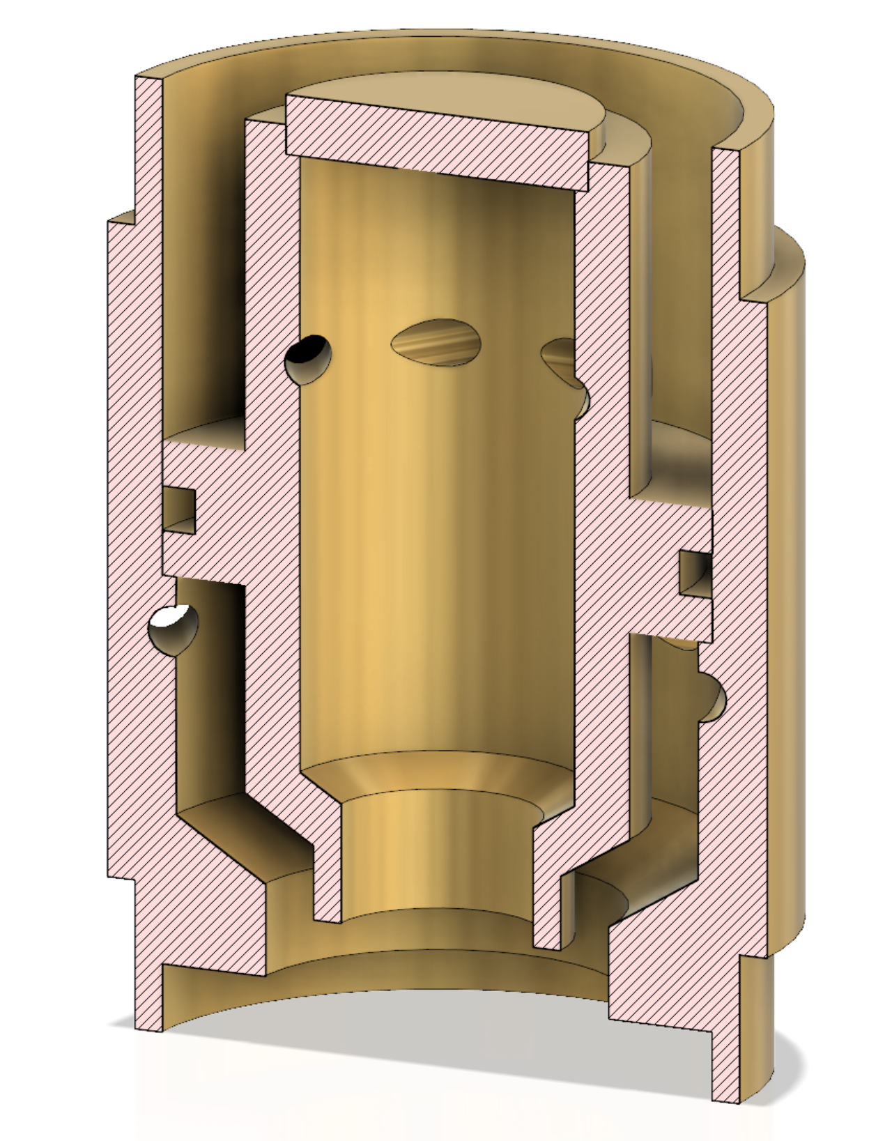
Tentative design of a coaxial swirler element.
In our configuration the inner element will deliver LOX and the outer element will be fuel. The inner element is fed from the top while the outer element is fed from the side. The mass flow depends primarily on the entry holes. In any case, it is customary to control the pressure drop via the cross-sectional area of the entrance holes, i.e. the holes in the sides. And it is the size of these that we have to play with in our upcoming test series.
But how do these swirlers integrate into a single injector? It is easiest to show with an illustration, so I have made a rough model of a possible injector configuration below. As can be seen, the injector is divided into two layers. A layer where fuel flows from the cooling jacket and is distributed in the outer part of the injectors and then a layer that distributes LOX to the inner part of the injectors. It is seen that it is all made up from a number of plasma-cut plates (hence our plasma cutting project) and then a solid amount of black smithing and welding.
Model of BPM100 injector.
In this configuration, there are a total of 135 swirlers. But, as I said, it will depend on the coming experiments to clarify the final number and their location. In any case, many elements must be made, and that is why it is essential that their geometry is as simple as possible. It opens up for the possibility of cheap mass production if we can find someone with a CNC lathe. Alternatively, we must go full throttle on our own lathe.
[1] K. Ghorbanian, M.R. Soltani, M. Ashjaee, M.R. Morad, “Spray Characteristics of a Liquid-Liquid Coaxial Swirl Atomizer at Different Mass Flux Ratios”


5 Comments
Tamas Fabian · 14th January 2019 at 8:58 pm
Very interesting development. 🙂
How the fuel will stay liquid so closely coupled to the LOX?
Thomas Pedersen · 17th January 2019 at 10:14 pm
You mean in the injector? It will not freeze up, the flow velocity is too high.
Mikkel Ø. P. Blok-Wahlgreen · 16th January 2019 at 8:54 am
Very interesting indeed.
How do you make sure that both LOX and fuel will have the correct pressure over all the swirles injectors?
I know the above picture is a crude sketch, however, how will I ensure a degrading flow resistance from the inlet of eg. fuel and the out most injector ensuring equal pressure?
For the LOX you will have the opposite case going from the outer rim to the center. The two will help each other of cause, however then you will have a different mixture over a line from center to outer rim.
Of course your holes in the injectors may vary with radius placement in the injector plate, but then you have many different swirls rather than one injector swirl.
Thomas Pedersen · 17th January 2019 at 10:17 pm
The dimensions inside the injector are in general pretty large, hence the majority of the pressure drop is on the swirler inlet holes. Thus the pressure should be the same on all swirlers.
We are building a huge water flow teststand that should help us measure this before firing the engine for the first time.
Stefan Moosburg · 18th January 2019 at 12:16 am
Hi guys, as always over the years I am fascinated by your work. By comparing to one of my rocket motor re-engineering projects, your design reminded me somehow to an injector nozzle design from the 1940ies, used by Hellmuth Walter, Kiel for his rocket developments. I am sure you also studied his types of Hydrogen-Peroxide based rocket motors. If you are interested in more info about this or if you have any questions, don’t hesitate to contact me. Sometimes its just a small discussion that leads to new ideas which can help to simplify something. Best regards from Germany
Stefan
Comments are closed.