Dear readers,
Not long ago we received a nice item from PH Spaanteknik which has once again helped us with some CNC machining. Jakob has spent a lot of hours this time and we are very grateful.
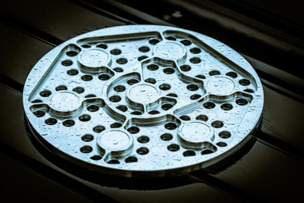
Illustration: Thomas Pedersen
So, what did Jakob mill for us? Well, he made the first prototype of something there’s going to be in our Spica rocket. It’s a nice gas manifold in stainless steel. As is clearly seen, it’s designed for CNC milling from the beginning. It would have required quite a lot of work on own little Deckel mill.
And what is its purpose? Yes, it’s hard to see, but it’s for the heat exchanger on Spicas BPM100 engine. As you probably remember, Nexø II flew with a 300-bar helium tank, which we used to maintain the pressure in the fuel tanks. The idea was to do the same with Spica. But we would need a lot of pressurized gas with two approx. 2,400-liter fuel tanks. With 20 bars in the tanks we would need approx. 48,000 standard liters (SL) of gas. Nexø II had 600 SL of helium on board, so we would need quite a lot of the expensive composite tanks if we choose that method. So, we’ll try something a little smarter.
The idea is to bring the gas for pressurization in liquid form instead. We have also previously seen that nitrogen is an excellent gas to use as pressurization gas, so we’ll also switch from helium to nitrogen. Nitrogen has an expansion factor of approx. 700 from liquid to gas, so the 48,000 SL can be brought as 68.5 liters in liquid nitrogen. Of course, to move nitrogen from liquid to gas, we need energy (heat), luckily that’s one thing that there is a lot of in a rocket engine. The perfect solution would be to get the heat from the engine. It does, however, provide a complicated interaction between the engine and the pressurizing system and, not least, it provides a pressurizing system which can only be tested in a full engine test. We won’t go so far.
Our system will instead consist of a separate burner which provides the necessary heat to evaporate the nitrogen. And when we are heating anyway, we will heat up the gas more so that it will expand more and thereby increase the factor of expansion from 700 to around 1000. By doing so we only need about 50 kg of nitrogen to propel the fuel.
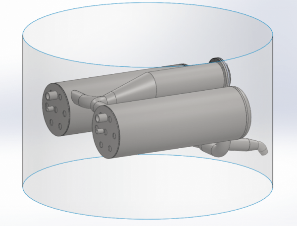
With a burning time of just about 50 seconds, if we run full throttle all the way to MECO, then we need to evaporate 1 kg of nitrogen per second. And additionally, we would also like to heat it to about 100 degrees. This gives a total energy consumption of 500 kW. Ethanol has a calorific value of about 30 MW/kg. We dilute our ethanol with 25% water, so the calorific value is probably only about 22 MW/kg. If we are to extract 500 kW out of such a burner, we must burn approx. 20 grams of fuel per second. Now, of course, it won’t be 100% efficient. The efficiency is one of the things that we’ll find during testing. From the above, however, it is hardly particularly clear how the manifold is included in such a burner and heat exchanger, so let’s look at Thomas Madsen’s design in Solidworks. First, look at the overall system. We see here the burner in the middle and two heat exchangers. Of course, it all fits within Spica’s diameter of 950 mm. The fact that there are two heat exchangers is because there is one for the fuel tank and one for the LOX tank, so the pressure can be controlled individually.
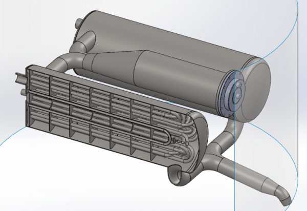
When we look inside one of the heat exchangers, we see a lot of pipes. In these pipes, the nitrogen will flow back and forth surrounded by the outer shell of the heat exchanger. There is 70 meters of tube inside each heat exchanger!
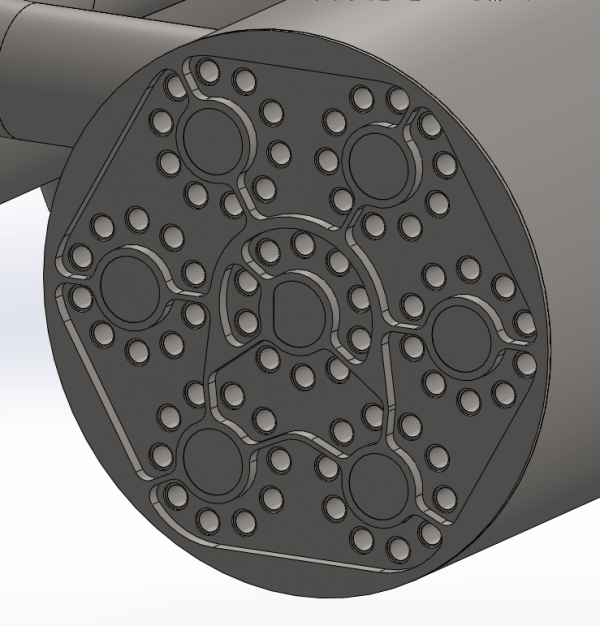
Finally we get to the manifold. In one end of each heat exchanger there is such a manifold which simply allows nitrogen to flow from one set of tubes to the next set of tubes through the heat exchanger. By doing so we get the necessary surface area needed to evaporate and heat 1 kg of nitrogen per second.
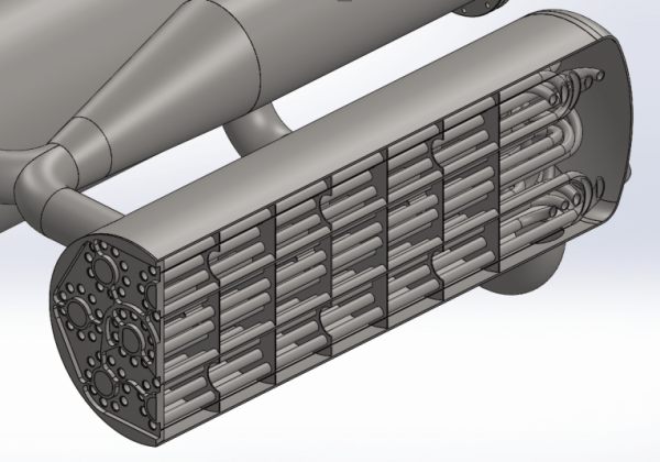
The next step will be to weld all the pipes to the manifold. When it’s done it will be a small work of art and it will be very exciting when we’re going to test it. As can be seen, there is no cooling in the system other than what comes from the hot nitrogen. This means that during operation, both burner and heat exchanger are likely to be red-hot. It will be quite a spectacular sight. It will initially be operated on the BPM5 test stand, although its fuel tanks are heavily oversized for the purpose. Initially, we will probably run water through the heat exchanger rather than nitrogen and simply measure the water temperature at the exit. But soon after that, we will test with nitrogen.


11 Comments
SVanHutten · 26th July 2019 at 1:53 am
Just wanted to say that designing a heat exchanger for the above stated purpose won´t be easy. As you intend to evaporate the LN2 and then further heat up the GN2 in the same exchanger, you will have to deal with two different fluids with very different specific heat, thermal conductivity and viscosity (as well as with the bubble laden intermediate phase), not to mention the vaporization enthalpy involved.
But it looks like you have anticipated trouble, as the exchanger is to be made of stainless steel and is likely to withstand running dry, or pure GN2 (it looks as beautiful as bulletproof).
As a side note, I wonder how are you going to control the flow of LN2 from the tank and through the exchanger, once the pressure rises downstream. If I am following your design idea, the whole pressurization system will have to cope with the high pressure, even the LN2 tank. If so, it looks easier (at least, without doing the math…) to mount the exchanger right inside the LN2 tank (some coils at the bottom), run the hot gases through it and then (if weight permits and performance justifies) use the residual heat in a second exchanger optimized for the GN2.
Anyway, just let me wish you good luck with your awesome project!
Mark Beard · 31st July 2019 at 2:23 pm
Such evaporators are extensively used in refrigeration systems, where multiphase refrigerant is both evaporated and superheated. It typically exists as a foam of liquid and gas phases together, (like the head on a beer), the proportion of gas increasing as the refrigerant flows through the evaporator. After complete evaporation, the gas is superheated above its boiling point at the working pressure. You are correct that superheating is less efficient than evaporation, but the efficiency of this section is less critical than the efficiency of the engine.
Max · 11th December 2019 at 3:13 pm
Heat exchangers are (ideally) constant pressure process machines, so ignoring friction losses (which are not insignificant in such long thin tubes, but irrelevant to my point) the pressure of the liquid going in will be equal to the pressure coming out. The benefit they provide comes in two forms in this case. First, it changes the phase from liquid to gas which dramatically reduces the required tank size, but that’s obvious and they stated that goal clearly in the article. The second benefit comes in the form of increasing the enthalpy (via increasing temperatire) of the gaseous nitrogen. A major issue with using high pressure fluids for medium pressure tank pressurization is that when you try to reduce that high pressure you inevitably must lower the gas temperature as the expansion process through most gas pressure regulators is close to adiabatic (for high flow rate regulators at least). Even expanding 40 bars of nitrogen to atmospheric pressure adiabatically can drop its temperature down to around or even lower the LOX temperatures. Ever wondered why the cold gas thruster plumes during Falcon 9 launch live streams appear white despite ejecting what should be a colorless gas (ie nitrogen)? What you’re seeing is nitrogen snow forming at the exit plane of the nozzle. So by increasing its enthalpy you can expand it from the original high pressure down to much lower pressures without worrying about cryogenic temperatures or nitrogen condensation downstream of the expansion device (either a regulator, control valve, or fixed orifice constriction). At least this is what I’ve been taught, but if I’m wrong in some way I would be more than interested in hearing why.
Ben Brockert · 18th August 2019 at 5:14 pm
To avoid two phase flow in your heat exchanger you could run the HX outlet above the critical pressure, which is 34 bar. You would still need a gas pressurization system to pressurize the nitrogen tank. Then it would transition to gas through your regulator or press valve.
Tube bundle HX design is not simple, and that assembly will be a challenge to build without leaks. I don’t doubt that it can be made to work with enough effort, but it seems like a failure of the “keep it simple” ethos that led to CS’s past successes. Engine heat exchangers are well established for warming pressurization gas (though usually it’s LOX-temperature helium). It’s good practice to test components independently before integrating, but sometimes a higher performance system is tightly coupled.
john ashcroft · 7th March 2021 at 6:06 pm
There maybe an easier way of pressurising the system. I don’t know if it will be lighter but should be simpler and lower cost.
You are looking at using a low performance rocket to vaporise and heat your rocket; I am going to suggest a different low performance rocket, taking a few ideas from Robert Truax
Have you considered a “hot water rocket”?
Essentially Water is superheated, probably resistively in a simple carbon steel tank. It can then be used to vaporise LOX directly, or could be used to pressurise and vaporise LN2. Pressurised LN2 could be vaporised by passing through etoh. (similar to Sea Dragon, though methane to pressurise RP-1)
Vaporized LOX or LN2 can be heated to 373K by direct injection of superheated water to the gas in the tanks. Not required for simple engine testing but should lower pressurant mass in rocket.
If you drop me an email I can run some numbers past you.
john ashcroft · 13th March 2021 at 6:39 pm
Some numbers: To vaporise 32kg of LOX to pressurise the LOX tank would require some 11kg of superheated water at 240C, 33bar. Tank maybe 8kg.
Some could be used to vaporise/pressurise tank of LN2, you would need 25kg of LN2 in a tank maybe 17kg, to be jetted into the etoh/water tank, vaporising/pressurising.
Using superheated water to heat presurants in tanks to 373 would save some weight but would add complexity.
john ashcroft · 27th March 2021 at 7:12 pm
??
John Ashcroft · 4th April 2021 at 12:04 am
Could you give an estimated mass for the system?
john ashcroft · 11th April 2021 at 10:20 am
You posted this as an answer to my question elsewhere, many thanks. I will cut and paste your reply here as it is appears more appropriate.
“Some numbers: To vaporise 32kg of LOX to pressurise the LOX tank would require some 11kg of superheated water at 240C, 33bar. Tank maybe 8kg.
Some could be used to vaporise/pressurise tank of LN2, you would need 25kg of LN2 in a tank maybe 17kg, to be jetted into the etoh/water tank, vaporising/pressurising.
Using superheated water to heat presurants in tanks to 373 would save some weight but would add complexity.”
john ashcroft · 11th April 2021 at 10:48 am
Thanks for the numbers.
There are other benefits from vaporising the LN2 and LOX with superheated water.
It looks like you are using the LN2 in blow down/vapak mode. This means bigger heavier tanks. The 50kg of LN2 at critical temp/pressure is 33bar. This will give you pressure at the end of blowdown of approx 24bar. But the density will be only 0.5 kg/l, so a 100litre tank, approximately 35kg.
But with heating with water you only need to have a LN2 tank for the fuel, and it only needs to hold to 20-22bar, there will be no losses from the heat exchanger. The LN2 can be at atm boiling point, density 0.8kg/l.
This adds up to a tank that is half the mass/kg of LN2 and only needed for pressurising the fuel. So about 8kg.
john ashcroft · 11th April 2021 at 11:29 am
The mass of hot water looks about right but the tank looks a little heavy. If I am right and the LN2 tank for 100l at 33 bar is about 35kg; then a 13litre tank for 11kg of water at 220C would be about 5kg.
Air lift tanks are mass produced and cheap, nominal working pressure of 200PSI, burst pressure is in the range of 750-12000PSI in aluminium and stainless steel. 3-4gallon, 12-16L models in the 3-5kg range.
https://www.thorairsuspension.com.au/airtanks
Comments are closed.