Translated by Bo Braendstrup
With only a few weeks until launch, it’s about time to have a look at what we actually plan to do above the waters of the Baltic Sea, and especially what kind of beast this rocket is, what makes it tick, and what kind of work it will perform.
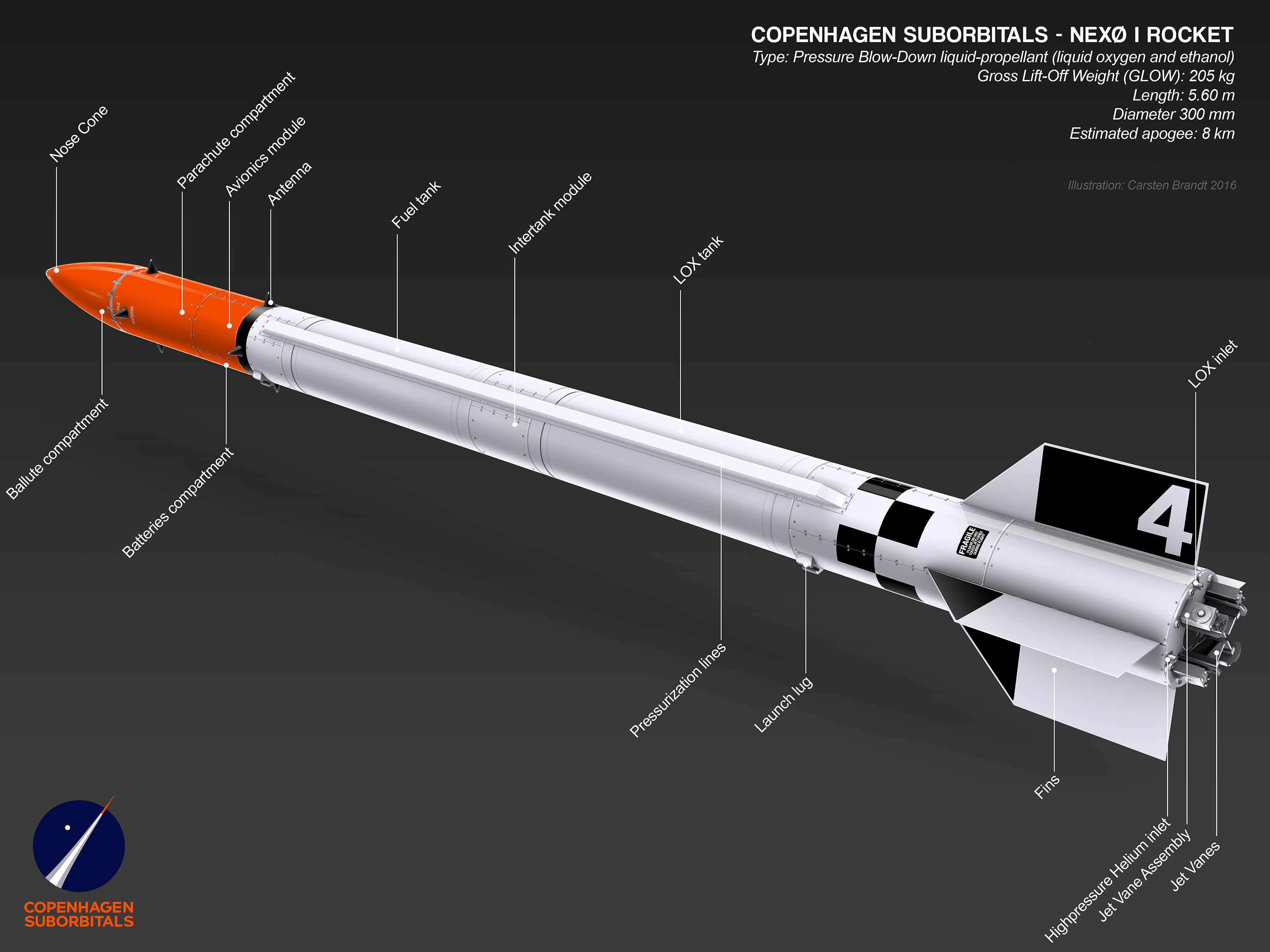
Illustration: Carsten Brandt (Fig. 1)
All who have followed out blogs will know that no specific part or component in this project is particularly advanced or mysterious.
All who have seen the rocket in the workshop, or hanging on the rail will know that the rocket is basically just a slender cylinder with fins at the base and a pointy top. It is difficult, if seen as above, to imagine what is beneath the skin.
First when a magical can opener is brought to use, the truth will be revealed, and you will get a sense of how many things have to intermesh in a delicate fashion.
For this reason Carsten Brandt have produced illustrations with the outer skin of the rocked peeled away. We can now show you the inner workings in all their glory.

Illustration: Carsten Brandt (Fig. 2)
Starting a bit backwards, by explaining what we will actually do above the Baltic Sea, and what physical work the rocket will perform during its mission, we must regrettably confess that in the physically sense, the rocket will do nothing: It ascends – and it then descends. The sum of the work performed is technically equal to ZERO!
The rocket will however make a tremendous amount of noise and produce lots hot air. Vast amounts of hot air, comprising of CO2 and water vapour. Nothing else!
It is the 30 second process during which the rocket will transform approximately 70 kg of pure liquid oxygen and lightly diluted alcohol into noise and hot air, that mark the magic moment in our quest to cross the Kármán line and thus reach outer space!
This brings about a quick tour through the workings of this “hot air generator”, aided by Carsten Brandt’s latest illustrations.
The illustration shows Nexø I, the first flight ready liquid fueled bi-propellant rocket in the Nexø class from the workshops at Copenhagen Suborbitals.
Carsten has dissected the rocket from top to bottom, letting you see the interiors. We start at the bottom and will work towards the top.
Jetvanes:
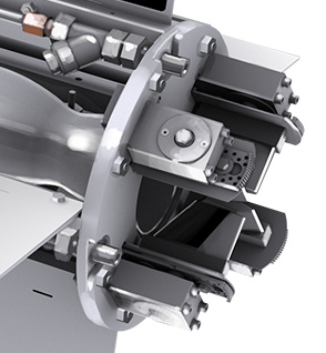
Illustration: Carsten Brandt (Fig. 3)
Ignoring the use of teflon gaskets and special LOX compatible lubricant, the vanes which deflect the engine exhaust to enable the rocket to remain on a true vertical course above the launch platform, is probably manufactured from the most advanced material in use at CS.
The vanes are made from an especially dense graphite which is one of a very few materials known to be able to withstand the extreme temperatures found in the fiery engine exhaust.
The graphite also tolerate the very large temperature variations, because of its very small thermal expansion coefficient. Many other materials would shatter immidiately when one side of the material is at 15-20 degrees C, while the other side is heated to almost 3000 degrees C in a fraction of a second.

Photo: Thomas Pedersen (Fig. 4)
Above: Jet vanes in protective foamlined case, ready for mounting.

Photo: Thomas Pedersen (Fig. 5)
Above: Jet vane assembly. Mounted on the servo actuated gear assembly.
Each of the four jet vanes is mounted in a stainless steel frame, mounted on a large gear that is driven by a smaller gear fixed on a servo actuator. The development and implementation of these parts has presented somewhat of a challenge, which Flemming Rasmussen has solved. A lot was learned from the successful Sapphire mission, resulting in this elegant small workhorse.
The bottom flange also houses four pipe sockets. These are the couplers for 1) The LOX tank fill pipe, 2) The LOX tank helium pressurisation pipe, 3) The fuel tank helium pressurisation pipe and 4) the engine purge pipe.
The engine, fins, valves:
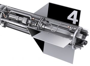
Illustration: Carsten Brandt (Fig. 6)
Rotating a jet vane is one thing, deflecting a jet exhaust another. The jet originates from the bottom part where the BMP-5 engine delivers 5000 N of thrust (this translates to approximately 500 kg lifting force) by combusting atomized liquid oxygen (which boils at -183 degrees centigrade) and liquid 75% alcohol (which freezes at -50 degrees centigrade).
The BPM-5 is the bottle-like tubular object in the center of the rocket frame, between the fins.
A short recap of how the engine works (dealt with in earlier blogs): The BPM-5 is a circumferentially liquid cooled bi-propellant liquid engine. The liquid oxygen (oxidizer) and the alcohol (fuel) are atomized by the injector at the top of the engine. The injector is made from one solid piece of aluminium, with holes and grooves drilled and milled in a complicated and precise way. The LOX is fed into the center of the top of the LOX dome, in which the injector is positioned.
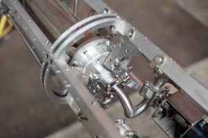
Photo: Thomas Pedersen (Fig. 7)
Above: The LOX dome and the center LOX pipe snaking in from the main valve outlet (turned 180 degrees compared to the overview drawing).
The alcohol, which also serves as coolant for the combustion chamber wall, made from standard grade steel, is first led to the bottom of the engine. Here a manifold receives the alcohol and guide it upward through narrow channels between the inner chamber wall and the outer wall. Here the alcohol-water mixture absorbs the significant heat generated by the combustion, thus cooling the wall so that it will retain its mechanical strength. First after this trip along the length of the engine will the alcohol be led into the injector through radial holes.
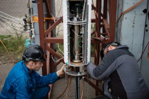
Photo: Thomas Pedersen (Fig. 8)
Above: A photo from a cold flow test, with the engine shown in its entire length.
The atomized mixture of LOX and fuel is ignited at the top of the combustion chamber, the length of which is determined by the time required to achieve the best possible combustion before the gases exit the engine through the throat. The throat is a restriction, acting as a barrier against chamber pressure loss.
The area of the throat aperture (together with the combustion chamber volume) is one of the most important parameters in rocket engine design. If the aperture ratio (between chamber volume and aperture area) is too large, the gases will have trouble escaping the chamber and the pressure can get excessively large and cause damage to the engine. On the other hand, if the aperture ratio is too small, the pressure will not be large enough to obtain the desired performance.
This is but one of many important factors that are part of the adjustments that can be juggled during the engine design process. As an example, a slightly reduced throat aperture area will result in a higher chamber pressure and higher exhaust velocity, resulting in larger thrust and a higher apogee.
But this will also stress the materials, and apply additional pressure on the inlet channels of the injector, resulting in a slightly lower LOX/fuel flow. A large number of factors have to be delicately weighted against each other.
Before I forget, I better mention the fins. Many have wondered why we need fins on a rocket so perfectly guided by Flemming Nyboe’s “utility software” and equipped with the best ever jet vanes manufactured by amateurs, in the known part of our galaxy.
There are several reasons. First of all, the fins moves Cp (Center of pressure) backwards, which increases the passive stability of the rocket. Furthermore, this rocket isn’t a solid giant like the Blue Origin rocket that just recently performed its fourth suborbital flight. Its low inertia makes it especially sensitive to any trajectory misalignment when it exits the launch rail. Should the rocket fancy doing a somersault at this point, then Nyboe’s software will probably not be able to get it back on track. So for safetys sake we use fins, to ensure a good trajectory until the guidance is “spot on”.
You have to strike a balance in this regard too. If the fins are too small they’re useless a low speeds. If they are too large the rocket will be sensitive to cross winds, and try to follow the direction af the wind.
We move further up the rocket:
Above the engine are the area that controls the flow of LOX and fuel. It is a very dense forest of twisted pipes, tight fittings, ball valves, and two very powerfull geared motors connected to the valves through the flexible transmission designed and manufactured by Martin Hedegaard for this specific purpose.
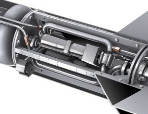
Illustration: Carsten Brandt (Fig. 9)
The illustration above shows the thin pressurisation pipes and the larger feed pipes from both the LOX tank and the fuel tank. To put the very tidy illustration in relief, I have found some photos depicting the real world reality:
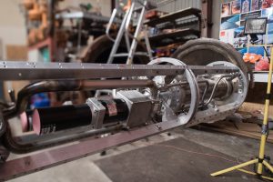
Photo: Thomas Pedersen (Fig. 10)
Above: This illustration shows why the valve compartment is much larger than the engine compartment. The DC motor with its gear, flexible transmission and ball valve is almost as long as the complete BPM-5 engine.
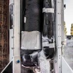
Photo: Jev Olsen (Fig. 11)
Above: Insulation for motors, gearboxes and feed pipe for LOX.
After the addition of insulation to the system of feed pipes, motors and gearboxes, necessary to enable the functionality despite the extreme temperature variations, not much detail remains to be seen. It might not look pretty, but it works!
The very large temperature variations present a major challenge in this type of rocket. Feed pipes for LOX and fuel must be kept apart (as far as possible), to avoid ice crystals forming in the mixture of water and alcohol, which might cause restrictions limiting the fuel flow. This would cause degraded cooling and a oxygen-rich combustion, leading to hotspots and subsequent burn-through in the chamber wall. Thus the LOX feed line is insulated to keep the cold IN.
DC motor and gearbox contains grease which risk becoming thick as pitch if becoming too cold. This is why the motor and gearbox is insulateed to keep the cold OUT.
The tanks:
Illustration: Carsten Brandt (Fig. 12)
Immediately above the valve compartment we find the LOX tank. The fuel tank further above is of identical construction, which means we will treat them as one, and have a look at choice of materials and positioning.
Both tanks are an integral part of the the rocket’s supporting structure. They are constructed from a rolled and longitudinally welded aluminium sheet, with end plates welded onto each end. Perforated baffles are placed at the bottom end plate, in part to counter slushing which could cause the rocket to veer from its intended trajectory, but in particular to avoid an outlet vortex (like you see when you remove the plug from the outlet of a filled bathtub) which would cause the fluids to flow AROUND the outlet, instead of flowing OUT the outlet.
Extending from the top and bottom end plates both, a collar and flange is welded on. The flange have holes matching the holes in the other flanges being part of the rocket’s supporting structure. Welding these collars/flanges with the required precision is a challenge, as aluminium buckle considerably during welding. If two joining flanges are not perfectly parallel, catastrophic disalignment would follow.
Apart from that, using aluminium is a clever decision. Aluminium is one of these wonderful materials that strengthens being worked mechanically (for instance when pressurising a tank) and increases its ductility and strength the colder it gets. And last, but not least, aluminium coats itself with a thin and tough coat of aluminium oxide, strong enough to protect the aluminium against corrosion – even when exposed to liquid oxygen! This makes aluminium an excellent choice for cryogenic applications. That aluminium is both cheap and light are other benefits.
Photo: Mads Stenfatt (Fig. 13)
Above: Peter Meincke pressure testing the two tanks for Nexø I. Ghis is done by filling the tanks with water, and then slowly pressurising in steps with additional water, until the pressure indicator reaches 150% of the nominal operating pressure.
We could have used a jerry can for the fueltank (if the jerry can could cope with the operating pressure), but have instead chosen to use two identical tanks. It is easier to deal with one subcontractors manufacturing identical devices, than several subcontractors manufacturing different tanks. As both tanks are also part of the supporting structure, them being identical is desirable from a structural point of view.
As can be seen in Carsten’s anatomical illustration above shows, the LOX tank is placed below the fuel tank. Placing the LOX tank above the fuel tank would require all of the external piping to be very well insulated. Instead we have chosen to feed the LOX through the shortest possible feed line between tank and main valve. The fuel feed line is laid along the outside of the LOX tank, requiring only a modest amount of insulation between the fuel pipe and the icy cold LOX tank wall.
Photo: Thomas Pedersen (Fig. 14)
Above: The cryogenic temperatures are challenging in many respects, as this photo of the open valve compartment with the Engine Controller Unit installed shows.
The humidity in the air condenses to thick layers of ice and snow everywhere. It is annoying, but not critical. It is however easy to imagine how a prolonged wait after filling the LOX tank will result in the rocket getting heavier by several kilos. It might be entertaining to do the calculations to determine the impact on apogee, but might be too nerdy to be regarded as an academic exercise.
Intertank module:
Illustration: Carsten Brandt (Fig. 15)
Lets have a look at what is happening in this small intertank module, placed between the two tanks:
This is where the fuel feed line exits the fuel tank end plate, is led outside the rocket, down along the LOX tank, and then in to the fuel valve inside the valve compartment, above the engine compartment. This is also where we have the LOX tank “christmas tree”. An identical “tree” is installed on top of the fuel tank.
For those not familiar with the term “christmas tree”, I’m sorry to inform you that we did not invent the term.
It is a common term for a complex design involving valves, piping and the like, making it possible to access a single inlet or outlet in a tank (or an oil well, for instance) in several simultaneous ways.
If you google “oil well christmas tree” images, you can see a wealth of wonderful examples of far more complex “christmas trees” than we will ever dream up. But we are not COMPLETELY out of the game!
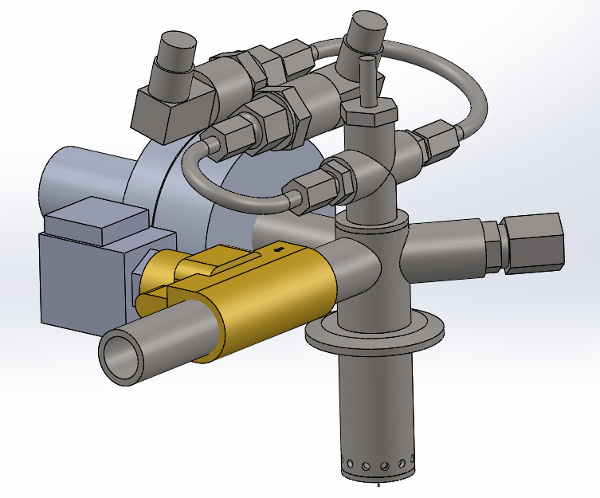
Illustration: CS (Fig. 16)
Above: 3D illustration showing the Nexø I “christmas tree”.
The christmas tree is a compact unit, comprising of:
1) Thermocouple, measures the temperature of the gas pocket, more interesting in the LOX tank.
2) Vent (ventilation) valve, used to prevent excessive tank pressure. The Engine Controller Unit will open the valve if a pressure limit parameter is exceeded. The valve is also opened to ventilate the tank during filling, to avoid back pressure. It is the vent valve that will frighten you with occasional loud “pops” during tanking, until you get used to the noise.
3) Burst disc, housed in the very substantial double flange on the side of the christmas tree. The disc will burst when the pressure reaches 27 bar, and is the very last line of defence against overpressure. The burst disc was responsible for the anticlimatic end to the first HEAT-2X engine test. A lucky outcome after all, as the LOX tank could have ruptured.
4) A pressure sensor for measuring the tank pressure.
5) An inlet port, for the pressurisation (helium) gas.
6) A diffusor in the bottom of the tree (immersed inside the tank) for radial distribution of the pressurisation gas.
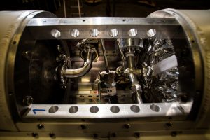
Photo: Carsten Olsen (Fig. 17)
Above: Christmas tree in the intertank module. Note the MLI blanket on top of the LOX tank.
And as already mentioned, an identical gadget is mounted on top of the fuel tank … which brings us another meter an a half up the rocket, to the avionics drum.
Avionics Drum:
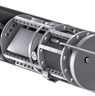
Illustration: Carsten Brandt (Fig. 18)
I have lost count on many times I have seen Jesper Rosendal and other members unmount the avionics drum to make small adjustments and corrections. And when you see the contents, you’ll understand why. While the Engine Controller Unit in the valve compartment is best compared with the human brain’s cerebellum (a humble CSduino and an interface board), the avionics drum with everything needed for guidance, navigation, communications and power for the entire rocket, compares to the cerebrum and the brainstem.
We need to carry power on board. Not only enough to deliver the required current when needed, we have to be able to store the power for an extended period of time. This has mandated the installation of five NiMH batterypacks, each rated at 12 V and 4.5 Ah, which powers the rocket through the power distribution box.
Then there’s GPS, one Piksi and one Poxa GPS receiver with associated antennas, an Arduino Nano and a barometric pressure sensor.
GNC (Guidance and Navigation Computer, a CSduino and an IMU) senses the movements of the rocket, the engine chamber pressure and the ambient atmospheric pressure and reacts to these inputs according to a predetermined flight plan. The rocket is guided along a vertical path by controlling the jet vanes in the engine exhaust, to ensure that the rocket never leaves the designated launch area. After MECO (when active guidance is no longer possible, and the rocket continues on its trajetory like a bsllistic object while shedding speed), ambient pressure is monitored closely. This will have a large impact on the timing of the nose cone seperation. More on this later.
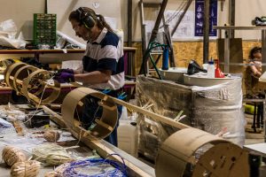
Photo: Mads Stenfatt (Fig. 19)
Above: Bo Brændstrup in the process of fitting the large cable harness with its plethora of connectors responsible for interconnecting all of the electronics modules. To ensure that the harness will fit on the finished rocket, the harness is laid out on a real size jig, manufactured for the purpose.
Finally we have the TM&TC (TeleMetry transmitters and TeleCommand receivers) controlled by two CSduinos, and then 3 antennas (although 4 antenna horns are installed, one is a dummy installed for aerodynamic symmetry reasons).
The parachute compartment:
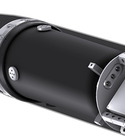
Illustration: Carsten Brandt (Fig. 20)
The parachute compartment is placed between the avionics drum and the nose cone. You may be surprised to learn that the parachute compartment is not filled to the brim with canopy fabric and lines. The electronics for the video camera and the video downlink transmitter is placed in the bottom of the compartment, powered from its batterypack placed in the avionics drum.
The parachute is packed in a container (a bag), placed inside an additional “bucket” in the parachute compartment. Some of the sturdiest brackets in the rocket are found in the parachute compartment. They have to carry the weight of the rocket while under the canopy, and additionally be able to handle some very powerful jerks and pulls.
The ballute is also fastened to one of these brackets, and the nose cone seperation, ballute deployment, canopy deployment and ballute release are all part of a carefully orchestrated sequence:
After MECO, while the rocket is in unpowered ballistic flight, the GNC will listen for the changes in ambient pressure with bated breath.
When the pressure has reached a minimum, the rocket is at its apogee (maximum altitude) and will start falling back to Earth.
After a certain rise in ambient pressure, the GNC will trigger the two airbaag gas generators placed inside the top of the nose cone. When these deploy, the pressure inside the nose cone will build rapidly, causing the 8 “dogbones” securing the nose cone to the parachute compartment to sever, resulting in the nose cone seperating into a free fall towards the Baltic Sea (and then again! … more on this later!).
The ballute made by seamstress Stenfatt will egress the nose cone at this time, and the wind pressure will start inflating the ballute to its inverted teardrop hape through the side air intake pockets. The ballute will now stabilise the rocket and curtail the downward speed.
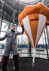
Photo: Jev Olsen (Fig. 21)
Above: Mads Stenfatt is testing his seamstress’ piece at Copenhagen Air Experience. The balloon like inverted teardrop shape is caused by the intake pockets scooping air into the interior volume of the ballute.
When the rocket has fallen to an appropriate altitude, the GNC will trigger a pyrotechnical line cutter, which will cut the line securing the ballute webbing to the bracket on the parachute compartment.
This will plunge the rocket into another free fall while the ballute webbing will pull the canopy container out of the parachute bucket, which again causes the stowed suspension lines to be pulled from the pockets in the parachute container. Finally the canopy will egress the container and inflate to its reefed state. The will give the rocket a good jerk, and then slow its descend.
The canopy in its reefed state? Yes, a reefing line has been drawn through the loops at the periphery of the canopy that also serve as suspension line attachment points. The length of the line restricts the opening of the canopy to roughly 50% of fully deployed area.
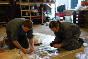
Photo: Thomas Pedersen (Fig. 22)
Above: Mads Stenfatt and Bo Brændstrup fastening the boxes containing the electronic timer and reefing line cutter to the parachute canopy.
After 15 seconds in this partially deployed state, another line cutter is triggered by an electronic timer packet with the canopy. The cutter wil sever the reefing line, causing the canopy to deploy fully as shown in the before/after photos below.
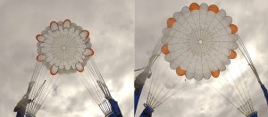
Photo: Ahmad Rahman (Fig. 23)
Above: Canopy during testing. Skydiver Ahmad Rahman has exited the jump plane and a static line deployed the canopy. Left: Reefed state, right: fully deployed. Notice the dark silhouette of the small dangling electronics box at seven o’clock in the right photo.
Although the electronics box containing line cutter and batteries is well protected inside the canopy, then a bag and then a parashute bucket, again protected by the nose cone containing the ballute and fastened with 8 metallic “dogbones”, redundancy has been provided: There are TWO electronics boxes containing a line cutter and a set of batteries each.
The rocket will now descend gracefully to a soft landing in the Baltic Sea, where it will be bobbing quietly until the recovery team arrives and secures it. We can then return home in an orderly fashion, and just prepare for the launch of Nexø II (yes, that’s correct – I’m preparing the production of all the decals in a few days!).
But … did I forget anything? Oh, yes – well, alright then!
The Nose Cone:
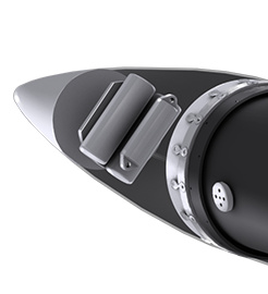
Illustration: Carsten Brandt (Fig. 24)
Nose cones for rockets come in many variations. Many rockets during the infancy of rocketry was just simple straight tapering cones, like you see on firework rockets and many smaller amateur rockets today.
If you want to reach higher speeds, supersonic speed for instance, you need to consider what shape the nose cone will have. Most are based on a geometric shape, a special circle segment, called an ogive.
A classical example is a secant ogive, as shown below:
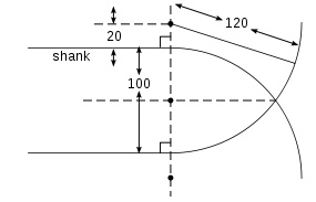
Illustration: Wikipedia (Fig. 25)
Above: A secant ogive of sharpness E = 120/100 = 1.2.
At transsonic speeds and above, you aim for a shape with smooth transitions and as few abrupt changes in shape as possible. It’s an intereesting field, and if you really make an effort you can gain additional range and less deviation from planned trajectory, compared to a simple shape.
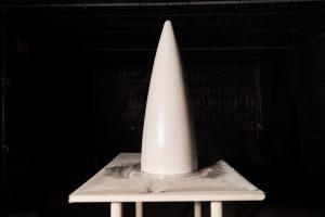
Photo: Carsten Olsen (Fig. 26)
Above: Shaped and primed nose cone, after a tireless effort by Rune Henssel.
Wolfgang Siegfried Haack (1902-1994), a german mathematician and aerodynamics expert, was so far ahead in his field during WW2 that his work on transsonic and supersonic aerodynamics was kept secret, because of its obvious significance for advances in weapons technology.

Photo: Thomas Pedersen (Fig. 27)
Above: Rune at work sanding the nose cone, which is mounted on the special nose cone lathe.
Haack researched, amongst other things, aerodynamic drag for different bodies at supersonic speeds and at the critical transsonic phase where the body transitions from supersonic to subsonic speed, or vice versa.
Through his research he developed a formula from which shapes later known as Haack-series shapes, was generated. Two special variants in the Haack-series is called LV-Haack (Length-to-Volume Optimized) and LD-Haack (Length-to-Diameter Optimized). The latter of these special nose cones is also called “Kármán Nose Cone”, eller “Kármán-Haack Ogive”, named after the hungarian-american mathematician and aerospace scientist Theodore von Kármán. The Kármán line (100 km – the limit to outer space) is also named after Theodore von Kármán.
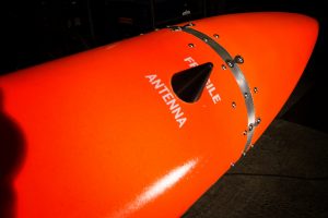
Photo: Thomas Pedersen (Fig. 28)
Above: The finished nose cone, fastened to the parachute compartment by the 8 metallic “dogbones”, designed to sever when the gas generators inside the top of the nose cone are triggered shorty after apogee.
There’s of course a formula for these nose cones that enables anybody to have a go at the Haack-series. First it is important to establish that the Haack-series doesn’t describe an ogive. An ogive is a geometric construction, while the Haack-series describes mathematical shapes which CANNOT be constructed geometrically.
Next it should be established that the Kármán nose cone is total overkill if you just want a reasonably well behaved rocket. For instance, the large Space Shuttle External Tank has a secant-ogive shape, as an optimised shape was considered unnecessary because of an almost countless number of dings and dents having a far greater impact on the aerodynamic characteristics.
Sometimes Rune will become as possessed, and he has apparently found it optimal to optimise the optimal optimum. Hence the shape HAD to be a “von Kármán nose cone”, which he then eagerly set out to produce. The result is a very nice, very strong, and very light cone, with a rigid flange at the base, perfectly fitted to the top flange on the parachute compartment.
As it is commonly known, nothing beats bettering a valued colleague, which begs the question: Had Rune made the CORRECT shape?
A couple of days ago, during my research in preparation for this blog, I took the liberty of testing the shape of the finished nose cone against the theoretical shape. This enables me to announce (with regrets), that Rune’s nose is flawless.
Nice job well done, which may be the reason why Rune has arranged for a special recovery parachute and GPS tracker to be included, thus wooing for a separate recovery operation for the nose cone.
Feel free to give the Haack-series a go on your own, here’s how:
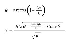
Illustration: Jørgen Skyt (Fig. 29)
Above: Formula for the Haack-series cone shapes.
Theta is derived from x in the upper formula, which then is substituted in the bottom formula to establish y.
L = length of cone.
R = Radius at cone base.
x = distance from cone top.
y = radius for a given value of x.
C can have many experimental values.
With C = 1/3 a LV-Haack shape is produced. Setting C = 0 produces a LD-Haack shape. The latter shape (LD-Haack) is the Kármán cone.
It might look like this in a spreadsheet:

Illustration: Jørgen Skyt (Fig. 30)
The above should provide amble opportunity for some nerdy passtime, to help alleviate the strenious period ahead, lasting until SPUTNIK leaves Copenhagen headed for Spaceport Nexø, marking the start of the Nexø 1 Launch Campaign.
Thank you for your attention!


4 Comments
Anonymous · 4th July 2016 at 10:17 pm
Thanks for this super-detailed insight! 🙂
Bruno F. Porto · 5th July 2016 at 4:11 pm
What you do is juts beautiful. It is too far…. But I hope one day be able to visit your workshop talk about rockets! Don’t you need a Liquid Propulsion Engineer eager to clean up the workshop after work??? 😀
Thank for all the inspiration. My best wishes for all of you.
anon · 9th July 2016 at 11:45 am
Some of the diagrams are horribly low resolution, can’t read any of it!
Rasmus Agdestein · 9th July 2016 at 12:00 pm
Hi.
Which diagrams are a problem ?
Comments are closed.